WORKSHOP MANUAL DIESEL ENGINE SM-E4B SERIES KiSC issued 01, 2013 A
TO THE READER This Workshop Manual tells the servicing personnel about the mechanism, servicing and maintenance of SM-E4B series. It contains 4 parts: "Information", "General", "Mechanism" and "Servicing". Q Information This section primarily contains information below. • Safety First • Specification • Performance Curve • Dimension Q General This section primarily contains information below.
I INFORMATION KiSC issued 01, 2013 A
INFORMATION CONTENTS 1. 2. 3. 4. SAFETY FIRST .............................................................................................................................. I-1 SPECIFICATIONS.......................................................................................................................... I-4 PERFORMANCE CURVES............................................................................................................ I-6 DIMENSIONS ...................................................
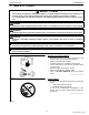
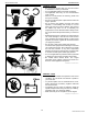
INFORMATION SM-E4B SERIES, WSM 1. SAFETY FIRST SAFETY FIRST • This symbol, the industry's "Safety Alert Symbol", is used throughout this manual and on labels on the machine itself to warn of the possibility of personal injury. Read these instructions carefully. • It is essential that you read the instructions and safety regulations before you try to repair or use this unit. DANGER • Indicates an imminently hazardous situation which, if not avoided, will result in death or serious injury.
INFORMATION SM-E4B SERIES, WSM OPERATE SAFELY • Do not use the machine after you consume alcohol or medication or when you are tired. • Put on applicable clothing and safety equipment. • Use applicable tools only. Do not use alternative tools or parts. • When 2 or more persons do servicing, make sure that you do it safely. • Do not touch the hot parts or parts that turn when the engine operates. • Do not remove the radiator cap when the engine operates, or immediately after it stops.
INFORMATION SM-E4B SERIES, WSM KEEP A GOOD AIRFLOW IN THE WORK AREA • If the engine is in operation, make sure that the area has good airflow. Do not operate the engine in a closed area. The exhaust gas contains poisonous carbon monoxide. WSM000001INI0006US1 DISCARD FLUIDS CORRECTLY • Do not discard fluids on the ground, down the drain, into a stream, pond, or lake. Obey related environmental protection regulations when you discard oil, fuel, coolant, electrolyte and other dangerous waste.
INFORMATION SM-E4B SERIES, WSM 2. SPECIFICATIONS Model Z482-E4B Z602-E4B Number of Cylinder 2 Type Vertical, Water-cooled, 4 cycle IDI diesel engine Bore × Stroke Total Displacement 67.0 × 68.0 mm (2.64 × 2.68 in.) 72.0 × 73.6 mm (2.83 × 2.90 in.) 479.0 cm3 (29.23 cu.in.) 599.0 cm3 (36.55 cu.in.) ISO Net Continuous 8.10 kW / 3600 min (rpm) (10.9 HP / 3600 min-1 (rpm)) 10.1 kW / 3600 min-1 (rpm) (13.5 HP / 3600 min-1 (rpm)) ISO / SAE Net Intermittent 9.30 kW / 3600 min-1 (rpm) (12.
INFORMATION SM-E4B SERIES, WSM Model D722-E4B D782-E4B Number of Cylinder D902-E4B 3 Type Vertical, Water-cooled, 4 cycle IDI diesel engine Bore × Stroke Total Displacement 67.0 × 68.0 mm (2.64 × 2.68 in.) 67.0 × 73.6 mm (2.64 × 2.90 in.) 72.0 × 73.6 mm (2.83 × 2.90 in.) 719.0 cm3 (43.88 cu.in.) 778.0 cm3 (47.48 cu.in.) 898.0 cm3 (54.80 cu.in.) ISO Net Continuous 12.2 kW / 3600 min (rpm) (16.3 HP / 3600 min-1 (rpm)) 11.9 kW / 3200 min (rpm) (16.0 HP / 3200 min-1 (rpm)) 15.
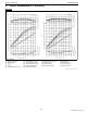
INFORMATION SM-E4B SERIES, WSM 3. PERFORMANCE CURVES Z482-E4B (1) (2) (3) (4) (5) Brake Horsepower Engine Speed B.S.F.C. Torque Gross Intermittent Torque (6) (7) (8) (9) (10) Net Intermittent Torque Net Continuous Torque Gross Intermittent B.H.P. Net Intermittent B.H.P. Net Continuous B.H.P. (11) (12) (13) (14) Net Intermittent B.S.F.C. Gross Torque Overload Torque Continuous Torque (15) (16) (17) (18) Gross B.H.P. Overload B.H.P. Continuous B.H.P. Overload B.S.F.C.
INFORMATION SM-E4B SERIES, WSM Z602-E4B (1) (2) (3) (4) Brake Horsepower Engine Speed B.S.F.C. Torque (5) (6) (7) (8) Gross Intermittent Torque Net Intermittent Torque Gross Intermittent B.H.P. Net Intermittent B.H.P. (9) Net Intermittent B.S.F.C. (10) Gross Torque (11) Overload Torque (12) Gross B.H.P. (13) Overload B.H.P. (14) Overload B.S.F.C.
INFORMATION SM-E4B SERIES, WSM D722-E4B (1) (2) (3) (4) (5) Brake Horsepower Engine Speed B.S.F.C. Torque Gross Intermittent Torque (6) (7) (8) (9) (10) Net Intermittent Torque Net Continuous Torque Gross Intermittent B.H.P. Net Intermittent B.H.P. Net Continuous B.H.P. (11) (12) (13) (14) Net Intermittent B.S.F.C. Gross Torque Overload Torque Continuous Torque (15) (16) (17) (18) Gross B.H.P. Overload B.H.P. Continuous B.H.P. Overload B.S.F.C.
INFORMATION SM-E4B SERIES, WSM D782-E4B (1) (2) (3) (4) Brake Horsepower Engine Speed B.S.F.C. Torque (5) (6) (7) (8) Gross Intermittent Torque Net Intermittent Torque Net Continuous Torque Gross Intermittent B.H.P. (9) (10) (11) (12) Net Intermittent B.H.P. Net Continuous B.H.P. Net Intermittent B.S.F.C. Gross Torque (13) (14) (15) (16) Overload Torque Gross B.H.P. Overload B.H.P. Overload B.S.F.C.
INFORMATION SM-E4B SERIES, WSM D902-E4B (1) (2) (3) (4) Brake Horsepower Engine Speed B.S.F.C. Torque (5) (6) (7) (8) Gross Intermittent Torque Net Intermittent Torque Gross Intermittent B.H.P. Net Intermittent B.H.P. (9) Net Intermittent B.S.F.C. (10) Gross Torque (11) Overload Torque (12) Gross B.H.P. (13) Overload B.H.P. (14) Overload B.S.F.C.
INFORMATION SM-E4B SERIES, WSM 4.
INFORMATION SM-E4B SERIES, WSM Z602-E4B 9Y1210785INI0008US0 I-12 KiSC issued 01, 2013 A
INFORMATION SM-E4B SERIES, WSM D722-E4B 9Y1210785INI0009US0 I-13 KiSC issued 01, 2013 A
INFORMATION SM-E4B SERIES, WSM D782-E4B 9Y1210785INI0010US0 I-14 KiSC issued 01, 2013 A
INFORMATION SM-E4B SERIES, WSM D902-E4B 9Y1210785INI0011US0 I-15 KiSC issued 01, 2013 A
G GENERAL KiSC issued 01, 2013 A
GENERAL CONTENTS 1. ENGINE IDENTIFICATION .......................................................................................................... G-1 [1] MODEL NAME AND ENGINE SERIAL NUMBER.................................................................. G-1 [2] E4B ENGINE .......................................................................................................................... G-3 [3] CYLINDER NUMBER .......................................................................................
GENERAL SM-E4B SERIES, WSM 1. ENGINE IDENTIFICATION [1] MODEL NAME AND ENGINE SERIAL NUMBER When contacting the manufacture, always specify your engine model name and serial number. The engine model and its serial number need to be identified before the engine can be serviced or parts replaced. Q Engine Serial Number The engine serial number is an identification number. It is marked after the engine model name. It indicates the engine series, the production year and month, and the lot number.
GENERAL SM-E4B SERIES, WSM (Continued) Production Month and Lot Number Month Engine Lot Number January A0001 ~ A9999 B0001 ~ February C0001 ~ C9999 D0001 ~ March E0001 ~ E9999 F0001 ~ April G0001 ~ G9999 H0001 ~ May J0001 ~ J9999 K0001 ~ June L0001 ~ L9999 M0001 ~ July N0001 ~ N9999 P0001 ~ August Q0001 ~ Q9999 R0001 ~ September S0001 ~ S9999 T0001 ~ October U0001 ~ U9999 V0001 ~ November W0001 ~ W9999 X0001 ~ December Y0001 ~ Y9999 Z0001 ~ * Alphabetical letters "I"
GENERAL SM-E4B SERIES, WSM [2] E4B ENGINE [Example : Engine Model Name D902-E4B-XXXX] The emission controls previously implemented in various countries to prevent air pollution will be stepped up as Non-Road Emission Standards continue to change. The timing or applicable date of the specific Non-Road Emission regulations depends on the engine output classification.
GENERAL SM-E4B SERIES, WSM 2. GENERAL PRECAUTION • When you disassemble, carefully put the parts in a clean area to make it easy to find the parts. You must install the screws, bolts and nuts in their initial position to prevent the reassembly errors. • When it is necessary to use special tools, use KUBOTA special tools. Refer to the drawings when you make special tools that you do not use frequently.
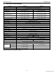
GENERAL SM-E4B SERIES, WSM 3. MAINTENANCE CHECK LIST To maintain long-lasting and safe engine performance, make it a rule to carry out regular inspections by following the table below. Service Interval Every Item 50 hrs 75 hrs *Checking fuel hoses and clamp bands (1) Oil pan depth (101 mm, 3.98 in.) (2) Oil pan depth Changing Engine (121 mm, 4.76 in.) oil (3) Extended oil pan depth (101 mm, 3.98 in.
GENERAL SM-E4B SERIES, WSM NOTE Engine Oil : • Refer to the following table for the suitable American Petroleum Institute (API) classification of engine oil according to the engine type (with internal EGR, external EGR or non-EGR) and the Fuel Type Used : (Low Sulfur, Ultra Low Sulfur or High Sulfur Fuels). Engine oil classification (API classification) Fuel Type Engines with non-EGR Engines with internal EGR Engines with external EGR High Sulfur Fuel [0.05 % (500 ppm) ≤ Sulfur Content < 0.
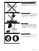
GENERAL SM-E4B SERIES, WSM 4. CHECK AND MAINTENANCE [1] DAILY CHECK POINTS Checking Engine Oil Level 1. Level the engine. 2. To check the oil level, draw out the dipstick (1), wipe it clean, reinsert it, and draw it out again. Check to see that the oil level lies between the two notches. 3. If the level is too low, add new oil to the specified level. IMPORTANT • When using an oil of different maker or viscosity from the previous, drain old oil. Never mix two different types of oil.
GENERAL SM-E4B SERIES, WSM Checking and Replenish Coolant 1. Without recovery tank (2) : Remove the radiator cap (1) and check to see that the coolant level is just below the port. With recovery tank (2) : Check to see that the coolant level lies between FULL "A" and LOW "B". 2. If coolant level is too low, check the reason for decreasing coolant. (Case 1) If coolant is decreasing by evaporation, replenish only fresh, soft water.
GENERAL SM-E4B SERIES, WSM [2] CHECK POINTS OF INITIAL 50 HOURS Changing Engine Oil • 1. 2. 3. 4. 5. • • • • • CAUTION Be sure to stop engine before changing engine oil. Start and warm up the engine for approx. 5 minutes. Place an oil pan underneath the engine. To drain the used oil, remove the drain plug (2) at the bottom of the engine and drain the oil completely. Screw the drain plug (2). Fill new oil up to upper line on the dipstick (1).
GENERAL SM-E4B SERIES, WSM Replacing Oil Filter Cartridge CAUTION Be sure to stop the engine before changing filter cartridge. Remove the oil filter cartridge (1) with the filter wrench. Apply a slight coat of oil onto the new cartridge gasket. To install the new cartridge, screw it in by hand. Over tightening may cause deformation of rubber gasket. 4. After the new cartridge has been replaced, the engine oil normally decrease a little.
GENERAL SM-E4B SERIES, WSM [3] CHECK POINT OF EVERY 50 HOURS Checking Fuel Hose 1. If the clamp (2) is loose, apply oil to the threads and securely retighten it. 2. The fuel hose (1) is made of rubber and ages regardless of the period service. Change the fuel hose together with the clamp every two years. 3. However, if the fuel hose and clamp are found to be damaged or deteriorate earlier than two years, then change or remedy. 4. After the fuel hose and the clamp have been changed, bleed the fuel system.
GENERAL SM-E4B SERIES, WSM [4] CHECK POINTS OF EVERY 75 HOURS Changing Engine Oil (for Optional Depth Oil Pans) • 1. 2. 3. 4. 5. • • • • • CAUTION Be sure to stop engine before changing engine oil. Start and warm up the engine for approx. 5 minutes. Place an oil pan underneath the engine. To drain the used oil, remove the drain plug (2) at the bottom of the engine and drain the oil completely. Screw the drain plug (2). Fill new oil up to upper line on the dipstick (1).
GENERAL SM-E4B SERIES, WSM [5] CHECK POINTS OF EVERY 100 HOURS Changing Engine Oil (for Standard Depth Oil Pans) • 1. 2. 3. 4. 5. • • • • • CAUTION Be sure to stop engine before changing engine oil. Start and warm up the engine for approx. 5 minutes. Place an oil pan underneath the engine. To drain the used oil, remove the drain plug (2) at the bottom of the engine and drain the oil completely. Screw the drain plug (2). Fill new oil up to upper line on the dipstick (1).
GENERAL SM-E4B SERIES, WSM Fan Belt Tension 1. Measure the deflection (A), depressing the belt halfway between the fan drive pulley and alternator pulley at specified force 98 N (10 kgf, 22 lbf). 2. If the measurement is not within the factory specifications, loosen the alternator mounting screws and relocate the alternator to adjust. Deflection (A) Factory specification 7.0 to 9.0 mm 0.28 to 0.35 in. (A) Deflection 9Y1210785GEG0013US0 Fan Belt Damage and Wear 1. 2. 3. 4.
GENERAL SM-E4B SERIES, WSM Cleaning Fuel Filter (Element Type only) 1. Close the fuel cock (3). 2. Unscrew the retaining ring (6) and remove the filter cup (5), and rinse the inside with kerosene. 3. Take out the element (4) and dip it in the kerosene to rinse. 4. After cleaning, reassemble the fuel filter, keeping out dust and dirt. 5. Bleed the fuel system. IMPORTANT • If dust and dirt enter the fuel, the fuel injection pump and injection nozzle will wear quickly.
GENERAL SM-E4B SERIES, WSM [7] CHECK POINTS OF EVERY 200 HOURS Replacing Oil Filter Cartridge (for Standard Depth Oil Pans) CAUTION Be sure to stop the engine before changing filter cartridge. Remove the oil filter cartridge (1) with the filter wrench. Apply a slight coat of oil onto the new cartridge gasket. To install the new cartridge, screw it in by hand. Over tightening may cause deformation of rubber gasket. 4. After the new cartridge has been replaced, the engine oil normally decrease a little.
GENERAL SM-E4B SERIES, WSM [8] CHECK POINTS OF EVERY 400 HOURS Replacing Fuel Filter Cartridge (Cartridge Type) Water and dust in fuel are collected in the filter cartridge. So, change the filter cartridge every 400 hours service. 1. Remove the used filter cartridge with filter wrench. 2. Apply a thin film of fuel to the surface of new filter cartridge gasket before screwing on. 3. Then tighten enough by hand. 4. Loosen the air vent plug to let the air out. 5. Start engine and check for fuel leakage.
GENERAL SM-E4B SERIES, WSM [9] CHECK POINTS OF EVERY 500 HOURS Cleaning Water Jacket and Radiator Interior CAUTION • Do not remove the radiator cap when the engine is hot. Then loosen cap slightly to the stop to relieve any excess pressure before removing cap completely. 1. Stop the engine and let cool down. 2. To drain the coolant, open the radiator drain plug (2) and remove the radiator cap (1). Then radiator cap (1) must be removed to completely drain the coolant. And open the drain cock (3). 3.
GENERAL SM-E4B SERIES, WSM Anti-Freeze • There are two types of anti-freeze available: use the permanent type (PT) for this engine. • Before adding anti-freeze for the first time, clean the radiator interior by pouring fresh, soft water and draining it a few times. • The procedure for mixing water and anti-freeze differs according to the maker of the anti-freeze and the ambient temperature. Basically, it should be referred to SAE J1034 standard, more specifically also to SAE J814c.
GENERAL SM-E4B SERIES, WSM [10] CHECK POINTS OF EVERY 1 OR 2 MONTHS Recharging CAUTION • When the battery is being activated, hydrogen and oxygen gases in the battery are extremely explosive. Keep open sparks and flames away from the battery at all times, especially when charging the battery. • When charging battery, remove battery vent plugs. • When disconnecting the cable from the battery, start with the negative terminal first.
GENERAL SM-E4B SERIES, WSM Battery Specific Gravity CAUTION • If battery acid (dilute sulfuric acid) gets on you it could cause blindness or burns, or could cause corrosion of machinery and tools so please be careful when handling. • Wear safety glasses and rubber gloves when performing battery maintenance and inspection (measuring specific gravity, replenishing water, or charging). • If the gas that is generated is ignited by an ignition source, it may explode so be very careful with sparks and fire.
GENERAL SM-E4B SERIES, WSM [11] CHECK POINT OF EVERY YEAR Replacing Air Cleaner Element 1. Remove used air cleaner element. 2. Replace new air cleaner element. NOTE • The air cleaner uses a dry element. Never apply oil to it. • Do not run the engine with filter element removed.
GENERAL SM-E4B SERIES, WSM [12] CHECK POINT OF EVERY 800 HOURS Checking Valve Clearance IMPORTANT • Valve clearance must be checked and adjusted when engine is cold. 1. Remove the cylinder head cover (1) and the glow plugs. 2. Align the "1TC" mark (2) on the flywheel and alignment mark (3) on the rear end plate so that the No. 1 piston comes to the compression top dead center. 3. Check the following valve clearance marked with "+" using a feeler gauge. 4.
GENERAL SM-E4B SERIES, WSM [13] CHECK POINTS OF EVERY 1500 HOURS CAUTION • Check the injection pressure and condition after confirming that there is nobody standing in the direction the fume goes. • If the fume from the nozzle directly contacts the human body, cells may be destroyed and blood poisoning may be caused. 9Y1210785GEG0031US0 Nozzle Spraying Condition 1. Set the injection nozzle to a nozzle tester, and check the nozzle spraying condition. 2.
GENERAL SM-E4B SERIES, WSM Nozzle Holder 1. Secure the nozzle retaining nut (7) with a vise. 2. Remove the nozzle holder (1), and take out parts inside. (When reassembling) • Assemble the nozzle in clean fuel oil. • Install the push rod (4), noting its direction. • After assembling the nozzle, be sure to adjust the fuel injection pressure. Tightening torque (1) (2) (3) (4) Nozzle Holder Adjusting Washer Nozzle Spring Push Rod Nozzle holder 35 to 39 N·m 3.5 to 4.
GENERAL SM-E4B SERIES, WSM [14] CHECK POINTS OF EVERY 3000 HOURS Injection Timing 1. Remove the injection pipes. 2. Remove the engine stop solenoid. 3. Turn the flywheel counterclockwise (viewed from flywheel side) until the fuel fills up to the hole of the delivery valve holder (3) for No. 1 cylinder. 4. After the fuel fills up to the hole of the delivery valve holder for No. 1 cylinder, turn back (clockwise) the flywheel around 1.6 rad (90 °). 5. Turn the flywheel counterclockwise to set at around 0.
GENERAL SM-E4B SERIES, WSM (Continued) NOTE • The liquid gasket is not required for assembling. • Shims are available in thickness of 0.20 mm (0.0079 in.), 0.25 mm (0.0098 in.), 0.30 mm (0.012 in.), 0.35 mm (0.014 in.) and 0.175 mm (0.00689 in.). Combine these shims for adjustments. • Addition or reduction of shim (0.025 mm, 0.00098 in.) delays or advances the injection timing by approx. 0.0044 rad (0.25 °).
GENERAL SM-E4B SERIES, WSM Checking Injection Pump (Fuel Tightness of Pump Element) 1. Remove the engine stop solenoid. 2. Remove the injection pipes and glow plugs. 3. Install the injection pump pressure tester to the injection pump. 4. Install the injection nozzle (2) jetted with the proper injection pressure to the injection pump pressure tester (1). (Refer to the photo.) 5. Set the speed control lever to the maximum speed position. 6. Run the starter to increase the pressure. 7.
GENERAL SM-E4B SERIES, WSM [15] CHECK POINTS OF EVERY 2 YEARS Replacing Intake Air Line 1. 2. 3. 4. Loosen the clamp (2). Remove the intake air hose (1) and clamp (2). Replace new intake air hose (1) and new clamp (2). Tighten the clamp (2). NOTE • To prevent serious damage to the engine, keep out any dust inside the intake air line.
GENERAL SM-E4B SERIES, WSM Replacing Fuel Hoses and Clamp Bands 1. Loosen the clamp (2) and remove the fuel hose (1). 2. Replace new fuel hose (1) and new clamp (2). 3. Tighten the clamp (2). CAUTION • Stop the engine when attempting the check and change prescribed above. (When bleeding fuel system) 1. Fill the tank with fuel and open the cock (4). ([B] only.) 2. Loosen the air vent plug (3) of the fuel filter a few turns. 3. Screw back the plug when bubbles do not come up any more. 4.
GENERAL SM-E4B SERIES, WSM Cleaning Water Jacket and Radiator Interior CAUTION • Do not remove the radiator cap when the engine is hot. Then loosen cap slightly to the stop to relieve any excess pressure before removing cap completely. 1. Stop the engine and let cool down. 2. To drain the coolant, open the radiator drain plug (2) and remove the radiator cap (1). Then radiator cap (1) must be removed to completely drain the coolant. And open the drain cock (3). 3.
GENERAL SM-E4B SERIES, WSM (Continued) (Anti-freeze) • There are two types of anti-freeze available: use the permanent type (PT) for this engine. • Before adding anti-freeze for the first time, clean the radiator interior by pouring fresh, soft water and draining it a few times. • The procedure for mixing water and anti-freeze differs according to the maker of the anti-freeze and the ambient temperature. Basically, it should be referred to SAE J1034 standard, more specifically also to SAE J814c.
GENERAL SM-E4B SERIES, WSM 5. SPECIAL TOOLS Diesel Engine Compression Tester (for Injection Nozzle) Code No. • 07909-30208 (Assembly) • 07909-30934 (A to F) • 07909-31211 (E and F) • 07909-31231 (H) • 07909-31251 (G) • 07909-31271 (I) • 07909-31281 (J) Application • Use to measure diesel engine compression and diagnostics of need for major overhaul.
GENERAL SM-E4B SERIES, WSM NOTE • The following special tools are not provided, so make them referring to the figure. 9Y1210785GEG0043US0 Injection Pump Pressure Tester Application • Use to check fuel tightness of injection pumps. A Pressure gauge full scale : More than 29.4 MPa (300 kgf/cm2, 4270 psi) B PF 1/2 C Copper gasket D Flange (Material Steel) E Hex. nut 27 mm (1.1 in.
GENERAL SM-E4B SERIES, WSM Valve Guide Replacing Tool Application • Use to press out and press fit the valve guide. A 220 mm (8.66 in.) B 80 mm (3.1 in.) C 40 mm (1.6 in.) D 20 mm dia. (0.79 in. dia.) E 9.960 to 9.980 mm dia. (0.3922 to 0.3929 in. dia.) F 5.50 to 5.70 mm dia. (0.217 to 0.224 in. dia.) G 25 mm dia. (0.98 in. dia.) H 6.00 to 6.10 mm dia. (0.237 to 0.240 in. dia.) I 5.0 mm (0.20 in.) J 18 mm dia. (0.71 in. dia.) K 10.6 to 10.7 mm dia. (0.418 to 0.421 in. dia.) L 6.
GENERAL SM-E4B SERIES, WSM Flywheel Stopper Application • Use to loosen and tighten the flywheel screw. A 20 mm (0.79 in.) B 15 mm (0.59 in.) C 10 mm dia. (0.39 in. dia.) D 30 mm (1.2 in.) E 8.0 mm (0.31 in.) F 200 mm (7.87 in.) 9Y1210785GEG0047US0 Crankshaft Bearing 1 Replacing Tool Application • Use to press out and press fit the crankshaft bearing 1. Q Press Out A 135 mm (5.31 in.) B 72 mm (2.8 in.) C 40 mm radius (1.6 in. radius) D 10 mm (0.39 in.) E 22 mm (0.87 in.
GENERAL SM-E4B SERIES, WSM Crank Sleeve Setter (for Z482/D722-E4B, D782-E4B) Application • Use to fix the crankshaft sleeve. (1) Auxiliary Socket for Pushing A 130 mm (5.12 in.) B 112 mm (4.41 in.) C 107 mm (4.21 in.) D 82 mm (3.2 in.) E 72 mm (2.8 in.) F 67 mm (2.6 in.) G 47 mm (1.8 in.) H 37.00 to 37.20 mm (1.457 to 1.464 in.) I 17 mm (0.67 in.) J 5.0 mm dia. (0.20 in. dia.) K 52 mm dia. (2.0 in. dia.) L 40 mm dia. (1.6 in. dia.) M 10 mm (0.39 in.) N 33 mm (1.3 in.
1 ENGINE KiSC issued 01, 2013 A
MECHANISM CONTENTS 1. ENGINE BODY........................................................................................................................... 1-M1 [1] HALF-FLOATING HEAD COVER ........................................................................................ 1-M1 [2] CLOSED BREATHER .......................................................................................................... 1-M1 [3] PISTON (Z602-E4B, D782-E4B, D902-E4B) .....................................................
ENGINE SM-E4B SERIES, WSM 1. ENGINE BODY [1] HALF-FLOATING HEAD COVER The rubber packing is fitted in to maintain the cylinder head cover 0.5 mm (0.02 in.) or so off the cylinder head. This arrangement helps reduce noise coming from the cylinder head. (1) Cylinder Head Cover (2) Rubber Packing 9Y1210785ENM0001US0 [2] CLOSED BREATHER Closed breather system has been adopted to prevent the release of blow-by gas into the atmosphere.
ENGINE SM-E4B SERIES, WSM [3] PISTON (Z602-E4B, D782-E4B, D902-E4B) Piston's skirt is coated with molybdenum disulfide*, which reduces the piston slap noise and thus the entire operating noise. *Molybdenum disulfide (MoS2) The molybdenum disulfide (1) serves as a solid lubricant, like a Graphite or Teflon. This material helps resist metal wears even with little lube oil. (1) Molybdenum Disulfide 9Y1210785ENM0003US0 [4] OIL PAN (Z602-E4B, D902-E4B) The oil pan is extended under the gear case.
ENGINE SM-E4B SERIES, WSM 2. COOLING SYSTEM [1] COOLING FIN (Z602-E4B, D902-E4B) The cooling fin is set up around the oil passage in the gear case. Therefore, the temperature of oil is decreased by the wind generated by the cooling fan.
SERVICING CONTENTS 1. TROUBLESHOOTING.................................................................................................................1-S1 2. SERVICING SPECIFICATIONS ..................................................................................................1-S4 3. TIGHTENING TORQUES..........................................................................................................1-S12 [1] TIGHTENING TORQUES FOR GENERAL USE SCREWS, BOLTS AND NUTS...............
ENGINE SM-E4B SERIES, WSM 1.
ENGINE SM-E4B SERIES, WSM Symptom Engine Revolution Is Not Smooth Either White or Blue Exhaust Gas Is Observed Either Black or Dark Gray Exhaust Gas Is Observed Deficient Output Excessive Lubricant Oil Consumption Fuel Mixed into Lubricant Oil Probable Cause Solution Reference Page Fuel filter clogged or dirty Replace G-17 Air cleaner clogged Clean or replace G-14 Fuel leak due to loose injection pipe retaining nut Tighten retaining nut 1-S31 Injection pump malfunctioning Repair or repl
ENGINE SM-E4B SERIES, WSM Symptom Probable Cause Reference Page Solution Water Mixed into Lubricant Oil Head gasket defective Replace 1-S32 Cylinder block or cylinder head flawed Replace 1-S51 Low Oil Pressure Engine oil insufficient Replenish Oil strainer clogged Clean 1-S34 Relief valve stuck with dirt Clean – Relief valve spring weaken or broken Replace – Excessive oil clearance of crankshaft bearing Replace 1-S63 Excessive oil clearance of crankpin bearing Replace 1-S62 Ex
ENGINE SM-E4B SERIES, WSM 2. SERVICING SPECIFICATIONS ENGINE BODY Item Factory Specification Allowable Limit 0.145 to 0.185 mm 0.00571 to 0.00728 in. – Z482-E4B D722-E4B D782-E4B 2.85 to 3.23 MPa 29.0 to 33.0 kgf/cm2 413 to 469 psi 2.26 MPa 23.0 kgf/cm2 327 psi Z602-E4B D902-E4B 3.53 to 4.02 MPa 36.0 to 41.0 kgf/cm2 512 to 583 psi 2.55 MPa 26.0 kgf/cm2 370 psi – 10 % or less 0.50 to 0.70 mm 0.020 to 0.027 in. – – 0.05 mm 0.002 in. −0.10 to 0.10 mm −0.0039 to 0.0039 in. 0.30 mm 0.012 in.
ENGINE SM-E4B SERIES, WSM Item Factory Specification Allowable Limit Open 0.87 rad (50 °) before B.D.C. – Close 0.26 rad (15 °) after T.D.C. – – 1.2 mm 0.047 in. Free Length 31.3 to 31.8 mm 1.24 to 1.25 in. 28.4 mm 1.12 in. Setting Load / Setting Length 65 N / 27.0 mm 6.6 kgf / 27.0 mm 15 lbf / 1.06 in. 55 N / 27.0 mm 5.6 kgf / 27.0 mm 12 lbf / 1.06 in. Oil Clearance 0.016 to 0.045 mm 0.00063 to 0.0017 in. 0.15 mm 0.0059 in. • Rocker Arm Shaft O.D. 10.473 to 10.484 mm 0.41233 to 0.
ENGINE SM-E4B SERIES, WSM Item Factory Specification Allowable Limit Cam Height [Z482/D722/D782-E4B] Intake 26.88 mm 1.058 in. 26.83 mm 1.056 in. [Z482/D722/D782-E4B] Exhaust 25.88 mm 1.019 in. 25.83 mm 1.017 in. [Z602/D902-E4B] Intake and Exhaust 26.88 mm 1.058 in. 26.83 mm 1.056 in. Camshaft Journal to Cylinder Block Bore Oil Clearance 0.050 to 0.091 mm 0.0020 to 0.0035 in. 0.15 mm 0.0059 in. • Camshaft Journal O.D. 32.934 to 32.950 mm 1.2967 to 1.2972 in.
ENGINE SM-E4B SERIES, WSM Factory Specification Allowable Limit Clearance 0.0900 to 0.120 mm 0.00355 to 0.00472 in. 0.15 mm 0.0059 in. Clearance 0.040 to 0.080 mm 0.0016 to 0.0031 in. 0.15 mm 0.0059 in. Connecting Rod Alignment – 0.05 mm 0.002 in. Crankshaft Side Clearance 0.15 to 0.35 mm 0.0059 to 0.012 in. 0.50 mm 0.020 in. – 0.02 mm 0.0008 in. Oil Clearance 0.020 to 0.051 mm 0.00079 to 0.0020 in. 0.15 mm 0.0059 in. • Crank Pin O.D. 33.959 to 33.975 mm 1.3370 to 1.3375 in.
ENGINE SM-E4B SERIES, WSM Item Factory Specification Allowable Limit 0.028 to 0.059 mm 0.0011 to 0.0023 in. 0.20 mm 0.0079 in. O.D. 43.934 to 43.950 mm 1.7297 to 1.7303 in. – • Crankshaft Bearing 3 I.D. 43.978 to 43.993 mm 1.7315 to 1.7320 in. – Cylinder Liner [Z482/D722/D782-E4B] I.D. 67.000 to 67.019 mm 2.6378 to 2.6385 in. 67.150 mm 2.6437 in. Cylinder Liner [Z602/D902-E4B] I.D. 72.000 to 72.019 mm 2.8347 to 2.8353 in. 72.150 mm 2.8406 in. Cylinder Liner [Oversize : 0.25 mm (0.
ENGINE SM-E4B SERIES, WSM LUBRICATING SYSTEM Item Factory Specification Allowable Limit More than 49 kPa 0.50 kgf/cm2 7.1 psi – At Rated Speed 197 to 441 kPa 2.00 to 4.50 kgf/cm2 28.5 to 64.0 psi 147 kPa 1.50 kgf/cm2 21.3 psi Inner Rotor to Outer Rotor Clearance 0.030 to 0.14 mm 0.0012 to 0.0055 in. – Outer Rotor to Pump Body Clearance 0.070 to 0.15 mm 0.0028 to 0.0059 in. – Inner Rotor to Cover Clearance 0.0750 to 0.135 mm 0.00296 to 0.00531 in.
ENGINE SM-E4B SERIES, WSM FUEL SYSTEM Item Factory Specification Allowable Limit Injection Pump [Z482/D602-E4B] Injection Timing (3600 min-1(rpm)) 0.3186 to 0.3447 rad (18.25 to 19.75 °) before T.D.C. – Injection Pump [D722-E4B] Injection Timing (3200 min-1(rpm)) 0.3360 to 0.3621 rad (19.25 to 20.75 °) before T.D.C. – Injection Pump [D782-E4B] Injection Timing (3200 min-1(rpm)) 0.2837 to 0.3097 rad (16.25 to 17.75 °) before T.D.C.
ENGINE SM-E4B SERIES, WSM ELECTRICAL SYSTEM Item Factory Specification Allowable Limit Approx. 1.1 Ω – Glow Plug Resistance Starter (Electromagnetic Drive Type) • Commutator O.D. 28.0 mm 1.10 in. 27.0 mm 1.06 in. • Difference O.D. Less than 0.05 mm 0.002 in. 0.40 mm 0.016 in. • Mica Undercut 0.50 to 0.80 mm 0.020 to 0.031 in. 0.20 mm 0.0079 in. • Brush Length 16.0 mm 0.630 in. 10.5 mm 0.413 in. O.D. 30.0 mm 1.18 in. 29.0 mm 1.14 in. • Difference O.D. Less than 0.02 mm 0.
ENGINE SM-E4B SERIES, WSM 3. TIGHTENING TORQUES Screws, bolts and nuts must be tightened to the specified torque using a torque wrench, several screws, bolts and nuts such as those used on the cylinder head must be tightened in proper sequence and the proper torque. 9Y1210785ENS0003US0 [1] TIGHTENING TORQUES FOR GENERAL USE SCREWS, BOLTS AND NUTS When the tightening torques are not specified, tighten the screws, bolts and nuts according to the table below.
ENGINE SM-E4B SERIES, WSM [2] TIGHTENING TORQUES FOR SPECIAL USE SCREWS, BOLTS AND NUTS NOTE • For "*" marked screws, bolts and nuts on the table, apply engine oil to their threads and seats before tightening. • The letter "M" in Size × Pitch means that the screw, bolt or nut dimension stands for metric. The size is the nominal outside diameter in mm of the threads. The pitch is the nominal distance in mm between two threads. Dimension × Pitch N·m kgf·m lbf·ft *Cylinder head cover screw M6 × 1 9.
ENGINE SM-E4B SERIES, WSM 4. CHECKING, DISASSEMBLING AND SERVICING [1] CHECKING AND ADJUSTING (1) Engine Body Compression Pressure 1. Run the engine until it is warmed up. 2. Stop the engine. 3. [a] Nozzle Hole Adaptor Setting : Remove the air cleaner, the muffler and all injection nozzles. [b] Glow Plug Hole Adaptor Setting : Remove the air cleaner, the muffler, the breather tube, the head cover and all glow plugs. 4. [a] Nozzle Hole Adaptor Setting : Set a compression tester (Code No.
ENGINE SM-E4B SERIES, WSM Checking Valve Clearance IMPORTANT • Valve clearance must be checked and adjusted when engine is cold. 1. Remove the cylinder head cover (1) and the glow plugs. 2. Align the "1TC" mark (2) on the flywheel and alignment mark (3) on the rear end plate so that the No. 1 piston comes to the compression top dead center. 3. Check the following valve clearance marked with "+" using a feeler gauge. 4.
ENGINE SM-E4B SERIES, WSM (2) Lubricating System Engine Oil Pressure 1. Remove the engine oil pressure switch, and set an oil pressure tester. (Code No. : 07916-32032) 2. Start the engine. After warming up, measure the oil pressure of both idling and rated speeds. 3. If the oil pressure is less than the allowable limit, check the following.
ENGINE SM-E4B SERIES, WSM (3) Cooling System Fan Belt Tension 1. Measure the deflection (A), depressing the belt halfway between the fan drive pulley and alternator pulley at specified force 98 N (10 kgf, 22 lbf). 2. If the measurement is not within the factory specifications, loosen the alternator mounting screws and relocate the alternator to adjust. Deflection (A) Factory specification 7.0 to 9.0 mm 0.28 to 0.35 in. (A) Deflection 9Y1210785GEG0013US0 Fan Belt Damage and Wear 1. 2. 3. 4.
ENGINE SM-E4B SERIES, WSM CAUTION • When removing the radiator cap, wait at least ten minutes after the engine has stopped and cooled down. Otherwise, hot water may gush out, scalding nearby people. 9Y1210785ENS0008US0 Radiator Cap Air Leakage 1. Set a radiator tester (1) and an adaptor (2) on the radiator cap. 2. Apply the specified pressure of 88 kPa (0.90 kgf/cm2, 13 psi), and measure the time for the pressure to fall to 59 kPa (0.60 kgf/cm2, 8.5 psi). 3.
ENGINE SM-E4B SERIES, WSM (4) Fuel System Injection Timing 1. Remove the injection pipes. 2. Remove the engine stop solenoid. 3. Turn the flywheel counterclockwise (viewed from flywheel side) until the fuel fills up to the hole of the delivery valve holder (3) for No. 1 cylinder. 4. After the fuel fills up to the hole of the delivery valve holder for No. 1 cylinder, turn back (clockwise) the flywheel around 1.6 rad (90 °). 5. Turn the flywheel counterclockwise to set at around 0.44 rad (25 °) before T.D.
ENGINE SM-E4B SERIES, WSM (Continued) NOTE • The liquid gasket is not required for assembling. • Shims are available in thickness of 0.20 mm (0.0079 in.), 0.25 mm (0.0098 in.), 0.30 mm (0.012 in.), 0.35 mm (0.014 in.) and 0.175 mm (0.00689 in.). Combine these shims for adjustments. • Addition or reduction of shim (0.025 mm, 0.00098 in.) delays or advances the injection timing by approx. 0.0044 rad (0.25 °).
ENGINE SM-E4B SERIES, WSM Fuel Tightness of Pump Element 1. 2. 3. 4. Remove the engine stop solenoid. Remove the injection pipes and glow plugs. Install the injection pump pressure tester to the injection pump. Install the injection nozzle (2) jetted with the proper injection pressure to the injection pump pressure tester (1). (Refer to the photo.) 5. Set the speed control lever to the maximum speed position. 6. Run the starter to increase the pressure. 7.
ENGINE SM-E4B SERIES, WSM CAUTION • Check the injection pressure and condition after confirming that there is nobody standing in the direction the fume goes. • If the fume from the nozzle directly contacts the human body, cells may be destroyed and blood poisoning may be caused. 9Y1210785GEG0031US0 Nozzle Spraying Condition 1. Set the injection nozzle to a nozzle tester, and check the nozzle spraying condition. 2. If the spraying condition is defective, replace the nozzle piece.
ENGINE SM-E4B SERIES, WSM Nozzle Holder 1. Secure the nozzle retaining nut (7) with a vise. 2. Remove the nozzle holder (1), and take out parts inside. (When reassembling) • Assemble the nozzle in clean fuel oil. • Install the push rod (4), noting its direction. • After assembling the nozzle, be sure to adjust the fuel injection pressure. Tightening torque (1) (2) (3) (4) Nozzle Holder Adjusting Washer Nozzle Spring Push Rod Nozzle holder 35 to 39 N·m 3.5 to 4.
ENGINE SM-E4B SERIES, WSM Battery Specific Gravity CAUTION • If battery acid (dilute sulfuric acid) gets on you it could cause blindness or burns, or could cause corrosion of machinery and tools so please be careful when handling. • Wear safety glasses and rubber gloves when performing battery maintenance and inspection (measuring specific gravity, replenishing water, or charging). • If the gas that is generated is ignited by an ignition source, it may explode so be very careful with sparks and fire.
ENGINE SM-E4B SERIES, WSM Motor Test CAUTION • Secure the starter to prevent it from jumping up and down while testing the motor. 1. Disconnect the battery negative cable from the battery. 2. Disconnect the battery positive cable from the battery. 3. Disconnect the leads from the starter B terminal. 4. Remove the starter from the engine. 5. Connect a jumper lead from the starter C terminal (1) to the battery positive terminal (2). 6.
ENGINE SM-E4B SERIES, WSM Magnet Switch Continuity Test 1. Check the continuity across the C terminal (1) and the B terminal (2) with a circuit tester, pushing in the plunger. 2. If not continuous or if a certain value is indicated, replace the magnet switch. (1) C Terminal (2) B Terminal [A] Electromagnetic Drive Type [B] Planetary Gear Reduction Type 9Y1210785ENS0018US0 No-load Dynamo Output 1. Disconnect the lead wires from the dynamo. 2.
ENGINE SM-E4B SERIES, WSM Continuity across Regulator's Terminals 1. Measure with a circuit tester according to the list below. NOTE • For this test, use only Analog Meter and do not use a high voltage tester such as a M Ω meter. • This check sheet shows the results of the test conducted by using the "Sanwa-made tester SP-10 and SP-15D" (Analog Meter). • Use of other testers than those above may show different measured results. Ω shall be used as the unit for the measuring range.
ENGINE SM-E4B SERIES, WSM Alternator on Unit Test (Before testing) • Before alternator on unit test, check the battery terminal connections, circuit connection, fan belt tension, charging indicator lamp, fuses on the circuit, and abnormal noise from the alternator. • Prepare full charged battery for the test. NOTE • Be careful not to touch the rotating engine parts while engine is running. Keep safety distance from the engine rotating parts. 1. Start the engine. 2.
ENGINE SM-E4B SERIES, WSM Engine Stop Solenoid Test (Energize to Run Type) 1. Disconnect the 3P connector (3) from the engine stop solenoid (1) wiring harness. 2. Remove the engine stop solenoid (1) from the engine. 3. Connect the jumper leads from the pulling coil terminal (6) to the switch (7), and from switch (7) to the battery positive terminal (10). 4. Connect the jumper leads from the holding coil terminal (5) to the switch (8), and from switch (8) to the battery positive terminal (10). 5.
ENGINE SM-E4B SERIES, WSM Draining Coolant CAUTION • Never remove radiator cap while operating or immediately after stopping. Otherwise, hot water will spout out from the radiator. Wait for more than ten minutes to cool the radiator, before opening the cap. 1. Prepare a bucket. Open the coolant drain cock. (1) Coolant Drain Cock 9Y1210785ENS0028US0 (2) External Components Alternator, Starter and Others 1. Remove the air cleaner and muffler. 2. Remove the engine stop solenoid (1). 3.
ENGINE SM-E4B SERIES, WSM Injection Pipes 1. Loosen the screws to the pipe clamp (2). 2. Detach the injection pipes (1). (When reassembling) • Sent compressed air into the pipes to blow out dust. Then, reassemble the pipes in the reverse order. Tightening torque Injection pipe retaining nut (1) Injection Pipe 25 to 34 N·m 2.5 to 3.5 kgf·m 18 to 25 lbf·ft (2) Pipe Clamp 9Y1210785ENS0031US0 Nozzle Holder Assembly and Glow Plug 1. Remove the overflow pipe (1). 2. Remove the nozzle holder assemblies (4).
ENGINE SM-E4B SERIES, WSM Rocker Arm and Push Rod 1. Remove the rocker arm bracket screws (2). 2. Detach the rocker arm assembly (1). 3. Remove the push rods (3). (When reassembling) • When putting the push rods (3) onto the tappets (4), check to see if their ends are properly engaged with the dimples. IMPORTANT • After installing the rocker arm, be sure to adjust the valve clearance. Tightening torque Rocker arm bracket screw (1) Rocker Arm Assembly (2) Rocker Arm Bracket Screws 9.81 to 11.2 N·m 1.
ENGINE SM-E4B SERIES, WSM Tappets 1. Remove the tappets (1) from the crankcase. (When reassembling) • Visually check the contact between tappets and cams for proper rotation. If defect is found, replace tappets. • Before installing the tappets, apply engine oil thinly around them. IMPORTANT • Do not change the combination of tappet and tappet guide. (1) Tappet 9Y1210785ENS0036US0 Valves 1. Remove the valve caps (4). 2.
ENGINE SM-E4B SERIES, WSM Oil Pan and Oil Strainer 1. Remove the oil pan mounting screws (2). 2. Remove the oil pan (1) by lightly tapping the rim of the pan with a wooden hammer. 3. Remove the oil strainer (3). (When reassembling) • After cleaning the oil strainer, check to see that the filter mesh in clean, and install it. • Visually check the O-ring (4), apply engine oil, and install it. • Securely fit the O-ring to the oil strainer.
ENGINE SM-E4B SERIES, WSM (4) Gear Case and Timing Gears Injection Pump, Fuel Feed Pump and Speed Control Plate (for Energize to Stop Type Engine Stop Solenoid) 1. Remove the socket head screws and nuts, and remove the injection pump (1). 2. Remove the screws and separate the speed control plate (2), taking care not to damage the governor spring (4). 3. Disconnect the governor spring (4) and remove the speed control plate (2). 4. Remove the fuel feed pump (3).
ENGINE SM-E4B SERIES, WSM (Continued) NOTE • Specific tool (1) : 1.2 mm (0.047 in.) diameter hard wire with its end hooked, overall length 200 mm (7.87 in.). The tip of wire is bent like the hook to hang governor springs. 1. Remove the socket head screws (3), and remove the engine stop solenoid (4). 2. Remove the screws and separate the speed control plate (6), taking care not to damage the governor spring (7). 3.
ENGINE SM-E4B SERIES, WSM (Continued) (When reassembling) 1. Move the fork lever (2) to the gear case side. 2. Hook the start spring (6) to the injection pump control rack pin (5). 3. Put the specific tool (7) through the fork lever hole of cylinder block (9) and hook the start spring (6). 4. Keep this spring slightly extended and install the injection pump (4). Make sure the control rod (8) should be pushed by the idling adjusting spring (1) and the pin (5) on the rod engages with the fork lever (2). 5.
ENGINE SM-E4B SERIES, WSM Fan Drive Pulley 1. Secure the flywheel to keep it from turning. 2. Remove the fan drive pulley screw. 3. Draw out the fan drive pulley with a puller. (When reassembling) • Install the pulley to crankshaft, aligning the mark (1) on them. • Apply engine oil to the fan drive pulley retaining screw. And tighten it. Tightening torque Fan drive pulley screw 118 to 127 N·m 12.0 to 13.0 kgf·m 86.8 to 94.0 lbf·ft (1) Alignment Mark 9Y1210785ENS0042US0 Gear Case 1.
ENGINE SM-E4B SERIES, WSM Idle Gear 1. Remove the external snap ring (3), the collar (2) and the idle gear (1). 2. Remove the idle gear shaft mounting screws (4). 3. Remove the idle gear shaft (5) (if necessary). (When reassembling) • Apply engine oil to the idle gear shaft mounting screw (4). And tighten them. • Install the idle gear, aligning the mark (6) on the gears referring to the photo. Tightening torque Idle gear shaft mounting screw (1) Idle Gear (2) Idle Gear Collar (3) External Snap Ring 9.
ENGINE SM-E4B SERIES, WSM Fuel Camshaft 1. Remove the retaining plate (6). 2. Remove the fork lever holder mounting screws (8), then draw out the injection pump gear (1) and fuel camshaft (7) with the governor fork assembly. (When reassembling) • Hook the governor spring (5) to the fork lever 2 (4) before installing the fork lever assembly to the crankcase.
ENGINE SM-E4B SERIES, WSM (5) Piston and Connecting Rod Connecting Rod Cap 1. Remove the connecting rod caps (1) using a bihexagonal 8 mm socket. (When reassembling) • Align the marks (a) with each other. (Face the marks toward the injection pump.) • Apply engine oil to the connecting rod screws and lightly screw it in by hand, then tighten it to the specified torque. If the connecting rod screw won't be screwed in smoothly, clean the threads.
ENGINE SM-E4B SERIES, WSM Piston Ring and Connecting Rod 1. Remove the piston rings using a piston ring tool. 2. Remove the piston pin (7), and separate the connecting rod (6) from the piston (5). (When reassembling) • When installing the ring, assemble the rings so that the manufacturer's mark (12) near the gap faces the top of the piston. • When installing the oil ring onto the piston, place the expander joint (10) on the opposite side of the oil ring gap (11). • Apply engine oil to the piston pin.
ENGINE SM-E4B SERIES, WSM (6) Flywheel and Crankshaft Flywheel 1. Secure the flywheel to keep it from turning using a flywheel stopper. (Refer to "SPECIAL TOOLS".) 2. Remove all flywheel screws (1) and then remove the flywheel (2). (When reassembling) • Set the No. 1 crankpin at the top dead center (T.D.C.). • Align the "1TC" mark (a) on the outer surface of the flywheel horizontally with the alignment mark (b) on the rear end plate.
ENGINE SM-E4B SERIES, WSM Crankshaft Assembly For Z482-E4B, D722-E4B 1. Remove the main bearing case screw 2 (1). 2. Draw out all the crankshaft. For Z602-E4B 1. Remove the main bearing case screw 2 (1). 2. Turn the crankshaft to set the crankpin of the cylinder to the horizontal directions (right or left). Then draw out all the crankshaft, holding the crankpins to the horizontal directions. For D782-E4B, D902-E4B 1. Remove the main bearing case screw 2 (1). 2.
ENGINE SM-E4B SERIES, WSM Main Bearing Case Assembly (Z482-E4B, D722-E4B, D782-E4B) 1. Remove the two main bearing case screws 1 (4), and remove the main bearing case assembly 1 (1), being careful with crankshaft bearing 3 (5). 2. Remove the main bearing case assembly 2 (2) and the main bearing case assembly (3) as above. Keep in mind, however, that the thrust bearing (7) is installed in the main bearing case assembly (3). (When reassembling) • Clean the oil passage in the main bearing cases.
ENGINE SM-E4B SERIES, WSM Main Bearing Case Assembly (Z602-E4B, D902-E4B) 1. Remove the two main bearing case screws 1 (4), and remove the main bearing case assembly 1 (1), being careful with crankshaft bearing 3 (5) (9). 2. Remove the main bearing case assembly 2 (2) and the main bearing case assembly (3) as above. Keep in mind, however, that the thrust bearing (8) is installed in the main bearing case assembly (3). (When reassembling) • Clean the oil passage in the main bearing cases.
ENGINE SM-E4B SERIES, WSM (7) Starter Electromagnetic Drive Type (1) Solenoid Switch Mounting Nut (2) Starter Drive Housing (3) Drive Lever (4) Gasket (5) Solenoid Switch (6) B Terminal Nut (7) C Terminal Nut (8) Snap RIng (9) Overrunning Clutch (10) Armature (11) Brush Spring (12) Connecting Lead (13) Rear End Frame (14) Gasket (15) Brake Spring (16) Brake Shoe (17) End Frame Cap (18) Screw (19) Yoke (20) Brush (21) Brush Holder (22) Through Bolt 1. 2. 3. 4. 5. 6. 7. 8. 9.
ENGINE SM-E4B SERIES, WSM Planetary Gear Reduction Type (1) Magnetic Switch Mounting Nut (2) Housing (3) Magnetic Switch (4) B Terminal Nut (5) C Terminal Nut (6) Drive Lever (7) Shaft Assembly (8) Overrunning Clutch (9) Connecting Lead (10) Mounting Screw (11) Armature (12) Yoke (13) Brush Holder (14) Rear End Frame (15) Through Bolt 1. Unscrew the C terminal nut (5), and disconnect the connecting lead (9). 2.
ENGINE SM-E4B SERIES, WSM (8) Dynamo (1) (2) (3) (4) (5) (6) (7) (8) Shaft Pulley Rotor Collar Bearing Stator Plate Bearing 1. Remove the nut and separate the plate (7). 2. Tap out the shaft (1) from the rotor (3). 3. Unscrew the screws and remove the stator (6). (When reassembling) • Take care the direction of the collar (4), the flat side should face to the pulley side. Tightening torque Pulley nut 40 to 44 N·m 4.0 to 4.
ENGINE SM-E4B SERIES, WSM (9) Alternator (1) (2) (3) (4) (5) (6) (7) (8) (9) (10) (11) (12) Pulley Drive End Frame Stator Bearing Retainer Plate Rotor Bearing Rear End Frame Rectifier IC Regulator Brush Holder Rear End Cover 1. Remove the pulley (1). 2. Remove the rear end cover (12). 3. Remove the brush holder (11). 4. Remove the IC regulator (10). 5. Remove the four screws holding the stator lead wires. 6. Remove the rectifier (9). 7. Remove the rear end frame (8). 8.
ENGINE SM-E4B SERIES, WSM [3] SERVICING (1) Cylinder Head and Valves Top Clearance 1. Remove the cylinder head. 2. With the piston at TDC, use grease to affix three or four plastigauges of a diameter 1.5 mm (0.059 in.) x 5.0 to 7.0 mm (0.20 to 0.27 in.) long to the crown of the piston; keep the gauges away from the intake valve and combustion chamber fittings. 3. Take the piston to an intermediate position, install the cylinder head and tighten the head bolts to the specified torque. 4.
ENGINE SM-E4B SERIES, WSM Cylinder Head Flaw 1. Prepare an air spray red check. 2. Clean the surface of the cylinder head with detergent (2). 3. Spray the cylinder head surface with the red permeative liquid (1). Leave it five to ten minutes after spraying. 4. Wash away the read permeative liquid on the cylinder head surface with the detergent (2). 5. Spray the cylinder head surface with white developer (3). 6. If flawed, it can be identified as red marks.
ENGINE SM-E4B SERIES, WSM Replacing Valve Guide (When removing) 1. Press out the used valve guide using a valve guide replacing tool. (Refer to "SPECIAL TOOLS".) (When installing) 1. Clean a new valve guide and valve guide bore, and apply engine oil to them. 2. Press in a new valve guide using a valve guide replacing tool. 3. Ream precisely the I.D. of the valve guide to the specified dimension. Valve guide I.D. (Intake and exhaust) Factory specification 6.010 to 6.025 mm 0.2367 to 0.2372 in.
ENGINE SM-E4B SERIES, WSM Correcting Valve and Valve Seat NOTE • Before correcting the valve and seat, check the valve stem and the I.D. of valve guide section, and repair them if necessary. • After correcting the valve seat, be sure to check the valve recessing. 1) Correcting Valve 1. Correct the valve with a valve refacer. Valve face angle Factory specification 0.79 rad 45 ° 2) Correcting Valve Seat 1. Slightly correct the seat surface with a 0.79 rad (45 °) valve seat cutter. 2.
ENGINE SM-E4B SERIES, WSM Free Length and Tilt of Valve Spring 1. Measure the free length (B) of valve spring with vernier calipers. If the measurement is less than the allowable limit, replace it. 2. Put the valve spring on a surface plate, place a square on the side of the valve spring. 3. Check to see if the entire side is in contact with the square. Rotate the valve spring and measure the maximum tilt (A). If the measurement exceeds the allowable limit, replace it. 4.
ENGINE SM-E4B SERIES, WSM Push Rod Alignment 1. Place the push rod on V blocks. 2. Measure the push rod alignment. 3. If the measurement exceeds the allowable limit, replace the push rod. Push rod alignment Allowable limit 0.25 mm 0.0098 in. (1) Push Rod 9Y1210785ENS0073US0 Oil Clearance between Tappet and Tappet Guide Bore 1. Measure the tappet O.D. with an outside micrometer. 2. Measure the I.D. of the tappet guide bore with a cylinder gauge, and calculate the oil clearance. 3.
ENGINE SM-E4B SERIES, WSM Idle Gear Side Clearance 1. Set a dial indicator with its tip on the idle gear. 2. Measure the side clearance by moving the idle gear to the front and rear. 3. If the measurement exceeds the allowable limit, replace the idle gear collar. Factory specification 0.20 to 0.51 mm 0.0079 to 0.020 in. Allowable limit 0.80 mm 0.031 in. Idle gear side clearance 9Y1210785ENS0076US0 Camshaft Side Clearance 1. Set a dial indicator with its tip on the camshaft. 2.
ENGINE SM-E4B SERIES, WSM Oil Clearance of Camshaft Journal 1. Measure the camshaft journal O.D. with an outside micrometer. 2. Measure the cylinder block bore I.D. for camshaft with a inside micrometer, and calculate the oil clearance. 3. If the oil clearance exceeds the allowable limit, replace the camshaft. Factory specification 0.050 to 0.091 mm 0.0020 to 0.0035 in. Allowable limit 0.15 mm 0.0059 in. Camshaft journal O.D. Factory specification 32.934 to 32.950 mm 1.2967 to 1.2972 in.
ENGINE SM-E4B SERIES, WSM (3) Piston and Connecting Rod Piston Pin Bore I.D. 1. Measure the piston pin bore I.D. in both the horizontal and vertical directions with a cylinder gauge. 2. If the measurement exceeds the allowable limit, replace the piston. Factory specification 20.000 to 20.013 mm 0.78741 to 0.78791 in. Allowable limit 20.05 mm 0.7894 in. Piston pin bore I.D. 9Y1210785ENS0083US0 Oil Clearance between Piton Pin and Small End Bushing 1. Measure the piston pin O.D.
ENGINE SM-E4B SERIES, WSM Connecting Rod Alignment NOTE • Since the I.D. of the connecting rod small end bushing is the basis of this check, check bushing for wear beforehand. 1. Install the piston pin into the connecting rod. 2. Install the connecting rod on the connecting rod alignment tool. 3. Put a gauge over the piston pin, and move it against the face plate. 4. If the gauge does not fit squarely against the face plate, measure the space between the pin of the gauge and the face plate. 5.
ENGINE SM-E4B SERIES, WSM Clearance between Piston Ring and Piston Ring Groove 1. Clean the rings and the ring grooves, and install each ring in its groove. 2. Measure the clearance between the ring and the groove with a feeler gauge. 3. If the clearance exceeds the allowable limit, replace the piston ring. 4. If the clearance still exceeds the allowable limit after replacing the ring, replace the piston. Second ring Clearance between piston ring and piston ring groove Oil ring Factory specification 0.
ENGINE SM-E4B SERIES, WSM Crankshaft Alignment 1. Support the crankshaft with V blocks on the surface plate at both end journals. 2. Set a dial indicator with its tip on the intermediate journal. 3. Measure the crankshaft alignment. 4. If the measurement exceeds the allowable limit, replace the crankshaft. Crankshaft alignment 0.02 mm 0.0008 in. Allowable limit 9Y1210785ENS0090US0 Oil Clearance between Crankpin and Crankpin Bearing 1. Clean the crankpin and crankpin bearing. 2.
ENGINE SM-E4B SERIES, WSM Oil Clearance between Crankshaft Journal and Crankshaft Bearing 1 1. Measure the O.D. of the crankshaft front journal with an outside micrometer. 2. Measure the I.D. of the crankshaft bearing 1 with an inside micrometer, and calculate the oil clearance. 3. If the oil clearance exceeds the allowable limit, replace the crankshaft bearing 1. 4.
ENGINE SM-E4B SERIES, WSM (Continued) (Reference) • Undersize crankshaft bearing 1 Undersize 0.20 mm 0.0079 in. 0.40 mm 0.016 in. Models Z482-E4B D722-E4B D782-E4B Z602-E4B D902-E4B Z482-E4B D722-E4B D782-E4B Z602-E4B D902-E4B Code Number Bearing Crankshaft bearing 1 02 Marking 15861-23910 020 US 1G460-23910 Crankshaft bearing 1 04 15861-23920 040 US 1G460-23920 • Undersize dimensions of crankshaft journal Models 0.20 mm 0.0079 in. 0.40 mm 0.016 in. Dimension A All models 1.8 to 2.
ENGINE SM-E4B SERIES, WSM Oil Clearance between Crankshaft Journal and Crankshaft Bearing 2 and Crankshaft Bearing 3 1. Put a strip of plastigage on the center of the journal. 2. Install the bearing case and tighten the bearing case screws 1 to the specified torque, and remove the bearing case again. 3. Measure the amount of the flattening with the scale, and get the oil clearance. 4. If the oil clearance exceeds the allowable limit, replace the crankshaft bearing 2 (crankshaft bearing 3). 5.
ENGINE SM-E4B SERIES, WSM (Continued) (Reference) • Undersize crankshaft bearing 2 and 3 Undersize Models Z482-E4B D722-E4B D782-E4B 0.20 mm 0.0079 in. Z602-E4B D902-E4B Bearing Code Number Crankshaft bearing 2 02 15694-23930 Crankshaft bearing 3 02 15861-23860 Crankshaft bearing 2 02 1G460-23930 Crankshaft bearing 3 02 1G460-23940 Marking 020 US • Undersize crankshaft bearing 2 and 3 Undersize Models Z482-E4B D722-E4B D782-E4B 0.40 mm 0.016 in.
ENGINE SM-E4B SERIES, WSM Replacing Crankshaft Sleeve (Z482-E4B, D722-E4B, D782-E4B) 1. Remove the used crankshaft sleeve (2). 2. Set the sleeve guide (3) to the crankshaft (1). 3. Heat a new sleeve to a temperature between 150 and 200 °C (302 and 392 °F), and fix the sleeve to the crankshaft as shown in figure. 4. Press fit the sleeve using the auxiliary socket for pushing (4). (Refer to "SPECIAL TOOLS".) NOTE • Mount the sleeve with its largely chamfered surface facing outward.
ENGINE SM-E4B SERIES, WSM Correcting Cylinder (Oversize) 1. When the cylinder is worn beyond the allowable limit, bore and hone it to the specified dimension. Factory specification Cylinder liner I.D. Allowable limit Finishing Z482-E4B D722-E4B D782-E4B 67.250 to 67.269 mm 2.6477 to 2.6483 in. Z602-E4B D902-E4B 72.250 to 72.269 mm 2.8445 to 2.8452 in. Z482-E4B D722-E4B D782-E4B 67.400 mm 2.6535 in. Z602-E4B D902-E4B 72.400 mm 2.8504 in. Hone to 2.2 to 3.0 μm Rz (87 to 110 μin. Rz) 2.
ENGINE SM-E4B SERIES, WSM (7) Starter Overrunning Clutch 1. Check the pinion and if worn or damage, replace the clutch assembly. 2. Check that the pinion turns freely and smoothly in the overrunning direction and does not slip in the cranking direction. 3. If the pinion slips or does not turn in both directions, replace the overrunning clutch assembly. NOTE • Do not wash off the grease in the overrunning clutch with the chemicals or oils.
ENGINE SM-E4B SERIES, WSM Commutator and Mica 1. Check the contact of the commutator for wear, and grind the commutator with emery paper if it is slightly worn. 2. Measure the commutator O.D. with an outside micrometer at several points. 3. If the minimum O.D. is less than the allowable limit, replace the armature. 4. If the difference of the O.D.'s exceeds the allowable limit, correct the commutator on a lathe to the factory specification. 5. Measure the mica undercut. 6.
ENGINE SM-E4B SERIES, WSM Brush Holder 1. Check the continuity across the brush holder and the holder support with a circuit tester. 2. If it conducts, replace the brush holder. 9Y1210785ENS0104US0 Armature Coil 1. Check the continuity across the commutator and armature coil core with resistance range of circuit tester. 2. If it conducts, replace the armature. 3. Check the continuity across the segments of the commutator with resistance range of circuit tester. 4.
ENGINE SM-E4B SERIES, WSM (8) Alternator Bearing 1. Check the bearing for smooth rotation. 2. If it does not rotate smoothly, replace it. 9Y1210785ENS0107US0 Stator 1. Measure the resistance across each lead of the stator coil with resistance range of circuit tester. 2. If the measurement is not within factory specification, replace it. 3. Check the continuity across each stator coil lead and core with resistance range of circuit tester. 4. If infinity is not indicated, replace it.
ENGINE SM-E4B SERIES, WSM Rectifier 1. Check the continuity across each diode of rectifier with resistance range of circuit tester. 2. The rectifier is normal if the diode in the rectifier conducts in one direction and does not conduct in the reverse direction. 9Y1210785ENS0112US0 IC Regulator 1. Check the continuity across the B terminal (2) and the F terminal (1) of IC regulator with resistance range of circuit tester. 2.
EDITOR : KUBOTA FARM & INDUSTRIAL MACHINERY SERVICE, LTD. 64, ISHIZU-KITAMACHI, SAKAI-KU, SAKAI-CITY, OSAKA, 590-0823, JAPAN PHONE : (81)72-241-1129 FAX : (81)72-245-2484 E-mail : ks_g.ksos-pub@kubota.com KUBOTA Corporation Printed in Japan 2012. 12, S, EI, EI, engusa Code No.