
Installation Guide
2of3
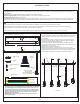
STEP 2 - Connections Fixture Wires to Jumper Wires
A. Strip back the clear wire covering on the 3 pendant cords to expose
the black, white and green wire. Leave at least approximately 3" of
cord length inside of the ceiling canopy. Strip each end of 3 fixture
wires.
B. Use supplied wire connectors (E) to connect fixture wires to Jumper
Wires (I). Twist connectors until wires are tightly joined together.
Wrap each connection with approved electrical tape.
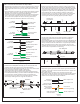
C. There are two sets up jumpers that have to be wired to the pendant
wires. The first set of jumpers will use the wires from 3 pendants.
The second set of jumpers will use the remaining wires from 2
pendants. Follow the illustrations below for correct wiring.
(1) White
Jumper Wire
(3) White wires
from fixture
(3) Black wires
from fixture
(1) Green
Jumper Wire
(1) Black
Jumper Wire
(3) Ground wires
from fixture
E
(1) White
Jumper Wire
(2) White wires
from fixture
(2) Black wires
from fixture
(1) Green
Jumper Wire
(1) Black
Jumper Wire
(2) Ground wires
from fixture
E
(1) White Jumper Wire
(1) Black Jumper Wire
(1) Green Jumper Wire
WIRINGFOR3SETSOFWIRES
WIRINGFOR2SETSOFWIRES
Figure 2
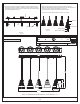
STEP 3 - Attach Inner Backplate Assembly to Outlet Box
A. Attach the Inner Backplate Assembly (A) onto the outlet box and
make two marks on the ceiling from a set of slot keyholes.
B. Remove the Inner Backplate Assembly (A). Using a 1/4” drill bit, drill
holes at each (2) locations marked on the ceiling.
C. Insert Wall Anchors (B) into drilled holes completely.
D. Pass supply wires and ground wire through the center hole of the
Inner Backplate Assembly (A). Attach the Inner Backplate Assembly
(A) to outlet box. Thread outlet box screws (not included) into
mounting holes on the outlet box and thread Screws (C) into Wall
Anchors (B). Hand tighten until snug with screwdrivers.
Supply Wires with
Ground Wire
Outlet Box Screw
(not included)
Outlet Box
A
C
D
Keyhole
Figure 3
Figure 4
STEP 4 - Test Fitting Ceiling Canopy to Inner Backplate Assembly
A. Remove mounting balls from the mounting screws. Fit the Ceiling
Canopy (B) to the mounting screws on the Inner Backplate (A) and
secure with mounting balls. Note: The Ceiling Canopy (B) should be
snug against the ceiling and the mounting balls. If not, adjust the
length of the nipple on the Inner Backplate (A) by unscrewing the
preassembled hex nut and lock washer and then screwing the
mounting screws in or out of the crossbar until the correct length is
achieved. Once the Ceiling Canopy (B) is secure, remove the
mounting ball and Ceiling Canopy (B) and proceed to Step 5.
Hex Nut and
Lock Washer
Mounting Screw
Mounting Ball
B
A
STEP 5 - Attach Lanyards
A. The purpose of the lanyard is to provide a means to support the
fixture hands free from the junction box while connecting the
electrical wires.
B. Turn the Button Stop so it may be inserted into a Inner Backplate slot.
Make sure the Button Stop is completely inside the Inner Backplate.
Slowly release the fixture to make sure it is supported by the Button
Stop. Proceed to the wiring steps in the next step. Once you are
complete with the wiring, the Lanyard will push into the junction box
when the fixture is placed for final mounting.
Lanyard
Button Stop
Inner Backplate
Slot
Figure 5
B
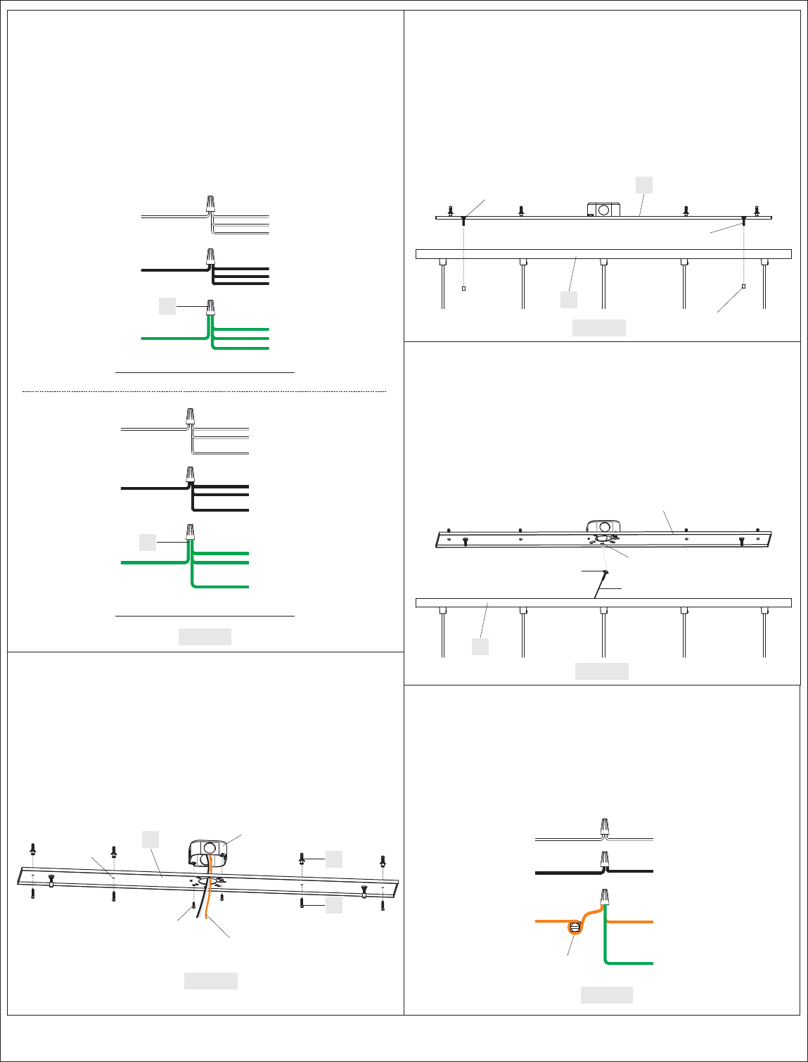
STEP 6 - Wire Connections
A. Wrap bare or green ground wire around green ground screw on the
crossbar, no less than 2 inches from the end of the wire. Tighten the
green ground screw.
B. Use standard wire connectors (not included) to make all wire
connections. Twist connectors until wires are tightly joined together.
Wrap each connection with approved electrical tape and carefully
stuff all the connected wires into the Outlet Box.
Green Ground Screw
on the Crossbar
White wire
from outlet box
White Jumper wire
Black wire from
outlet box (or Red)
Black Jumper wire
Bare, or Green
Ground wire
from outlet box
Ground wire
from Ceiling Canopy
Green Jumper wire
Figure 6