
Assembly Instructions

Assembly Instructions
IMPORTANT:
• ALL INSTALLATION WORK SHOULD BE DONE BY ACCREDITED PROFESSIONAL.
• SHUT OFF POWER SUPPLY AT FUSE OR CIRCUIT BREAKER!
• USE ONLY THE SPECIFIED BULBS. DO NOT EXCEED THE MAXIMUM WATTAGE!
For Customer Service, please
contact the place of purchase.
PREPARING FOR INSTALLATION
Note: This xture may be mounted close-to-ceiling as a semi-ush or with rods as a pendant. These are semi-ush directions.
Remove all of the contents from the carton. See the important notes above. Shut off the power at the circuit breaker and
completely remove the old xture from the ceiling, including the old mounting strap.
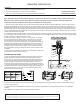
1. Take the mounting strap assembly from the parts bag. Mounting strap (B) contains several threaded holes. Two of mounting screws
(A) should be attached to mounting strap (B). You may need to tighten nuts (C) which hold these screws in place. If the screws are not
attached, please hold canopy (F) up to mounting strap (B). Line up the holes in canopy (F) with the holes in mounting strap (B) and insert
mounting screws (A) into mounting strap (B) so that mounting screws (A) protrude through the holes in canopy (F). Mounting screws (A)
are long, please test the canopy against the mounting strap to see how far you should insert the screws. Tighten nuts (C) onto mounting
screws (A) to hold the screws in place.
2. Pull the house wires through the center of mounting strap (B). Place mounting strap (B) over the junction box so that mounting screws
(A)areinalignmentwiththeholelocationsonthexture’scanopy(F).Securemountingstrap(B)tothejunctionboxwithmountingscrews
(D) and a screwdriver. Tighten the screws securely.
FINISHING THE INSTALLATION
6.Placethexture’scanopy(F)overmountingscrews(A)sothattheyprotrudethroughtheholesincanopy(F).Threaddeconuts(G)
onto mounting screws (A).
7.Installlightbulbs(notprovided)inaccordancewiththexture’sspecications.Donotexceedthemaximumrecommended
wattage.
Yourinstallationiscomplete.Turnonthepowerandtestthexture.
CONNECTING THE WIRES
5. Haveanassistantsupporttheweightofthexture.Refertothewiring
diagramandattachthexture’swirestothepowersupplywiresfrom
the junction box. Connect Hot to Hot, Neutral to Neutral, and Ground to
Ground. Twist the ends of the wire pairs together, and then twist on a wire
connector. Make sure all twists are in the same direction. If there is no
house ground wire coming from the junction box, locate ground screw (E)
onthemountingbracket/mountingstrapandwrapthexture’sgroundwire
around the ground screw. Use a screwdriver to tighten the top of ground
screw (E) onto the wires and into the mounting bracket/mounting strap.
Tuck the wires into the junction box.
House Wires
Fixture Wires
Hot
How to Identify the Fixture’s Wires
Hot Neutral Ground
Smooth
Ribbed
Bare Metal,
Green, or
Green Inner
Thread
Black
White
Black Inner
Thread
White Inner
Thread
CLEANING TIPS
Treat the xture gently! Regular cleaning will reduce the need for deep cleaning. For regular cleaning, turn off the light and wipe down the
xture with a clean lint-free cotton or microber cloth. Never spray cleaner directly onto the xture.
L
M
S
Step 1
Step 2
A
G
N
D
B
C
D
E
F
G
H
M
N
O
Q
K
L
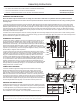
3. Refer to the “Step 1” diagram. Frame (L) is composed of four panels (1
and 2). The panels are two different sizes. Center rod (N) is on the wires,
butnotattachedtothexture.Screwcenterrod(N)ontopost(O)and
then connect it to the bottom of bracket (S). Use small bracket screws (P)
toattachbracket(S)withthexture’sbodyattachedtobothofpanels(1).
Slide panels (2) over the ends of connected panels (1) so that the holes
in panels (2) line up with the holes in panels (1). Use screws (T) to secure
the panels together. Frame (L) should look like the “Step 2” diagram when
completed.
4. Twist connector (K) onto the top threads of post (M) before screwing the
open threads onto swivel (H) of canopy (F).
M
L
2
1
1
S
T
R