Instruction Manual Wright Manufacturing 4600X Wedgewood Blvd Frederick, Md 21703 Wright ZTO serial # 62995 and higher WARNING: READ THIS MANUAL BEFORE USING For your safety and for proper operation and maintenance read carefully and keep readily available for future reference. 01/2013 Wright Manufacturing Inc.
Foreword Welcome to the progressive group of mowing professionals who use Wright mowers. We are focused on giving you advanced engineering and quality construction in each mower we build. This manual explains the features and promotes safer use of the mower. Please read it in its entirety and follow the instructions carefully so that you can have many years of safe and productive operation with your Wright product. This manual may contain information pertaining to European models also.
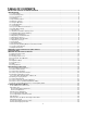
TABLE OF CONTENTS PRE-DELIVERY SERVICE OF MOWER BY DEALER ............................................................................................................... 3 1 INTRODUCTION ....................................................................................................................................................................... 5 1.1 Technical Data ........................................................................................................................................
6.9 Battery Service ............................................................................................................................................................... 26 6.10 Cutting Blades .............................................................................................................................................................. 27 6.11 Transporting / Tie Down Locations ............................................................................................................
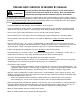
PRE-DELIVERY SERVICE OF MOWER BY DEALER WARNING Before proceeding with the Pre-Delivery Service of your mower, please read the safety instructions manual in its entirety. Only your authorized Wright dealer should perform the Pre-Delivery Service of the mower. The Wright ZTO is shipped completely assembled and has been adjusted and tested at the factory. However, due to the jostling of the shipping process and the delivery time lapse, the following items need to be repeated again before starting the mower.
Turn on the blade clutch switch. Run blades for approximately one minute. Next, engage and disengage the blades a few times about 10 seconds apart. If the blades do not start and stop in a few seconds each time, service the blade brake system. With the blades on, disengage the OPC switch to test the Operator Presence Control switch (OPC). A time delay has been added to the OPC system. The engine should die and the blades should stop with-in 4-7 seconds after leaving the seated position.
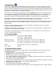
1 Introduction This mower is built to the highest standards in the industry. However, carelessness or operator error may result in serious bodily injury or death. Accident and hazard prevention are dependent upon the awareness, concern, wisdom, and proper training of the personnel involved in the operation, transport, maintenance, and storage of the equipment. Make sure every operator is properly trained and thoroughly familiar with all of the information in this manual before operating the equipment.
1.2.
operation of this equipment and be sure they read and follow the instructions in this safety manual and other material provided by Wright Manufacturing, Inc. before using or allowing others to operate the equipment. DO NOT operate this unit unless you carefully read, understand and follow the operation and safety instructions contained in this manual and the warning decals provided on the unit.
1.10 Prevent Fires WARNING Machine fires and structural fires can occur if a machine is stored before allowing it to cool, if debris is not removed from critical areas of the machine, or if the machine is stored near combustible materials. • Remove grass and debris completely from engine compartment and muffler area, and from on top of the mower deck, before and after operating machine, especially after mowing or mulching in dry conditions. • Always shut off fuel when storing or transporting.
• All operators of this mower should exercise caution when driving this mower at high speeds. Sudden acceleration or deceleration may cause serious injury. • DO NOT allow inexperienced persons to operate the mower until they have read and understood these safety instructions. Operate the mower at slower speeds while becoming familiar with it.
1.17 Operation on Slopes WARNING DO NOT operate on steep slopes. DO NOT operate the mower on slopes steeper than you can feel secure about the traction of the tires and the stability of the mower. DO NOT operate the mower on slopes at all when the grass is wet. DO NOT mow near drop-offs or near water. Keep the roll bar in the raised and locked position and use seat belt. There is a danger of suddenly sliding sideways or down the hill.
WARNING 1.19 Hydraulic Safety The hydraulic system on the Wright ZTO is not equipped with high pressure hydraulic hoses or any external high pressure hydraulic exposure. However, always use caution when servicing any hydraulic systems. 1.20 Responsibly Handling Waste Product and Chemicals Waste products, such as used oil, fuel, coolant, brake fluid and batteries, can harm the environment and people: • Do Not use beverage containers for waste fluids – someone may drink from them.
2 Warning, Safety and Instructional Decals • Specific safety warning decals are located on the equipment near immediate areas of potential hazards. • Keep all safety signs legible. Remove all grease, dirt and debris from safety signs and instructional decals. • Replace worn, damaged or missing safety decals. • If an attachment or accessory has been installed, make sure current safety decals are visible.
Warning, denotes potential hazardous situation which, if not avoided, could result in minor to serious injury or death Warning, rotating blades, Keep hands, feet and clothing away from rotating blades. Use safety glasses to avoid thrown material. To inspect blades or clean under side of cutter deck, apply parking brake and remove ignition key. Caution, rotating pulleys and belts. Keep shields and covers in place while machine is in operation.
• • • • • • • Fuel System Capacity: 14.5 Gal. (54.9 L) Type of Fuel: Unleaded regular gasoline, minimum 85 octane. Do not use gasoline containing more than 10% ethanol. Do not mix oil with gasoline. Fuel Filter: In line Fuel Shut Off: On / Off, In line Fuel gauge in left side fuel tank Safety Interlock System PTO switch must be disengaged, control handles in the OUT position to start the engine.
4 Machine Description & Overview The Wright ZTO is meant to solely cut, bag or mulch grass. The use for any other purpose is not recommended. Always keep the Roll Over Protection in the full up position and always wear your seatbelt.
4.1 Model and Serial Location 1. The plate is affixed on the right side in the engine compartment. 2. Stated on the plate will be the Model, date of assembly and serial number, these will be needed when ordering parts. 4.2 Operator’s Area 1 – Seat, Armrests and Seat Belt 4 – Motion Control Handles 7 – Control Panel 2 – Fuel Cap 3 – Left Fuel Tank w/ Gauge & Cup-Holder 5 – Foot Platform 6 – Deck Lift Lever and Height Adj.
4.3 Steering Control Levers The ZTO’s speed and direction are controlled by using two steering control handles. The handles can be moved forward and backward about a neutral position. Moving the control handle equal distance forward or backward the machine moves in a straight line. Inward Drive Position Right Turn Left Turn 4.4 Fuel System / Shut Off Valve The fuel shut off valve is located at the left rear behind the seat compartment.
4.6 Digital Hour Meter The ZTO is equipped with a digital hour meter. Refer to operating/reset instructions below. The programming specified is: Default display: Hours Press once (TMR1): Timer 1, press for 3 sec to reset Press twice (TMR2): Timer 2, press for 3 sec to reset Press three times (svc ENG): Will display time remaining until next service point, hold down to reset. The first interval is 8hr, thereafter 100hr.
4.9 Safety Switch System The Wright ZTO is equipped with a safety interlock system. The PTO must be disengaged, an operator in the seat and the control levers in the Out (Brake On) position in order to start the machine. Seat (OPC) Safety Switch Operator must remain seated while blades are engaged. To leave the seat, disengage blade switch and move the control arms to the outward (Brake/Parked) position. Seat Up Switch Mower will not start with seat in the “Up” position.
5.2 How to start the mower Before starting the engine • Make sure the control levers are in the Parked/Brake, outward position • Turn OFF the blade engaging switch if it is on. • Turn fuel valve to the “On” position. Note: The fuel valve is located on the left side, rear of the seat frame. Starting the engine •Start the engine according to the engine manufacturer’s recommendation, see engine manual. Set the throttle control lever near mid throttle. Set the choke lever to full choke.
WARNING 5.5 Driving the Mower Over a Curb To climb a curb, first see the Safety Instructions section of this manual, especially the parts on: • Initial Operating Safety Guidelines • Operation In Reverse • Operation In Forward Direction Next, raise the mower deck into the locked transport position. This is the highest position for the mower deck.
5.8 How to Perform the Tracking Adjustment First ensure that the tire pressure is equal on both rear drive tires (18-22 psi). Drive the mower on a level parking lot with the engine at full throttle. Check that the mower drives in a straight line when both hand controls are held to the full speed position. If not, park the mower and stop the engine. The adjustment is made by loosening the jam-nuts on the control rods (Fig. 1, at transaxle) (Fig.
6 SERVICE AND ADJUSTMENTS 6.1 Tire Maintenance and Pressure WARNING Excessively worn tire tread is dangerous on all hills. Replace drive tires with less than 3/32” of any tread groove left. Use tires with the tread pattern recommended by Wright Mfg., Inc. only. Keep the tire pressure in the drive tires between 18 and 22 psi. Lowering tire pressure will affect deck pitch. Always check pitch any time tire pressure is set below recommended pressures.
6.3 Belt Tension Adjustment The pump drive belt is self-adjusting, and requires no adjustment. The blade drive belt is self-adjusting also and requires no adjustment. Replace tension idler assembly if worn or failing to maintain proper tension. 6.3.1 Replacing the Drive Belt • • • • • • Stop the engine, remove the key and wait for all moving parts to stop. Remove engine to blade cutter deck belt. (Refer to “replacing the cutter deck belt” section) Raise rear the seat tray. Remove both cooling fans.
6.5 How to Move the Mower if the Engine Won’t Start Remove the R-clip from the neutral release arm (bypass valve). Pull arm outward and install R-clip. The control handles must be in the “In, Drive” positions to release the parking brake. (Closed) Run position 6.6 Hydraulic System (Open) Unlocked position WARNING Whenever servicing the hydraulic system, it is of the utmost importance to keep any dirt or debris from getting into the system. Clean off all parts before disassembly and assembly.
Expansion tank Expansion tank Right Transaxle Left Transaxle (b) Stationary Idler Pulley (c)Vent Plug (a) Filter Guard and Filter (a) Filter Guard and Filter WARNING 6.8 Transaxle Purging Procedure Lift the mower so that the rear wheels are off the ground. Be careful to support the mower so that it will not fall or tip while the system is bled of air. Open both bypass valves (see section 6.5). Start the machine and slowly move the control levers back and forth five or six times.
6.10 Cutting Blades WARNING In order to maintain to best cut, it is important that the blades are well sharpened and not damaged. Bent or cracked blades or blades with large nicks need to be replaced. Blades must be balanced after sharpening. To change the blades; • Stop engine, remove the key and wait for all moving parts to stop. • Engage parking brake. • Lift front of mower and secure in the raised position with jack stands. • Remove the blade bolt by turning counterclockwise.
This symbol means ATTENTION! YOUR SAFETY IS INVOLVED. The message that follows the symbol contains important information about safety. Carefully read the message. This Roll Over Protective Structure (ROPS) has been certified to industry and/or government standards. Any damage or alteration to the ROPS, mounting hardware, or seat belt voids the certification and will reduce or eliminate protection for the operator in the event of a rollover.
6.14 Spindle and Drive Pulley Split hub R&R • • • • Remove 2, ¼” bolts from split hub and install in threaded holes in hub. Slowly tighten each bolt, alternating as you tighten bolts against the pulley. The hub will separate from the pulley. Replace grade 8 bolts and install in reverse order using the assembly holes to tighten hub onto pulley and spindle shaft. Threaded Removal holes Assembly hole Tightening will separate the hub from the pulley Assembly hole 6.
6.16 Kawasaki / Briggs & Stratton Engine Manual / Maintenance It is very important that all users of this unit read and understand the Kawasaki / Briggs & Stratton Engine Owner’s Manual. These manuals contain; safety awareness, emissions, maintenance and warranty information that is critical for the care of your engine. Below is the periodic maintenance chart directly from the Kawasaki / Briggs & Stratton Owner’s Manuals, which is included with the sale of the ZTO.
Briggs and Stratton Maintenance chart Maintenance Chart First 5 Hours Change oil Every 8 Hours or Daily Check engine oil level Clean area around muffler and controls Clean finger guard / rotating screen Every 25 Hours or Annually Clean air filter* Every 50 Hours or Annually Change engine oil Replace oil filter Check muffler and spark arrester Every 250 Hours or Annually Change air filter Annually Replace air filter Replace spark plugs Clean air cooling system* Replace fuel filter Check valve clear
7 Electrical Schematic 32
8 ZTO Consumables / Maintenance Items ZTO Consumables / Maintenance Items P/N Description 11990116 13990007 13990039 17460012 17460017 17460018 17460021 18410012 24420030 39410004 39410007 42420002 42420004 45410002 45410005 45410020 52410003 52410006 BOLT, HEX 5/8 - 11 x 1 1/2 Z5 BLADE SPACER, 5/8 X 1/4 WASHER, 5/8 Z8 52410007 52420002 52420003 53490009 MODULE - TIME THROTTLE CABLE SWITCH, BLADE ON/OFF, RED SOLENOID RELAY, FOR MAIN HARNESS BLADE, 18" BLADE, 16 1/2" BLADE, 21" 53490019 71440001 714400
9 Decals 34
MAINTENANCE ITEM EN GI ITE NE MS SE E N BE OTE LO W FIR ST HO 8 UR S DA ILY EV ER Y HO 25 UR S EV ER Y1 HO 0 UR 0 S EV ER Y HO 200 UR S EV ER Y HO 300 UR S AN NU AL LY 10 Maintenance Interval Chart *2 Inspect for cracks in frame, cutter deck or other steel parts X X Inspect cutter deck belts for wear and alignment X Check all bolts and nuts for tightness (tighten as necessary) X Check transaxle oil reservoir level and fill as needed (use 15-50 motor oil) X Inspect drive belt, idler pulley(s) an
Maintenance Record Date Maintenance/Service Performed 36 Unit Hours Shop/Technician
WRIGHT MANUFACTURING, INC. POWER EQUIPMENT LIMITED WARRANTY THIS WARRANTY SUPERSEDES ALL PREVIOUS ON UNITS WITH A RETAIL SALES DATE ON OR AFTER 04/01/05 The WMI mower, including any defective part, must be returned to an Authorized WMI Service Dealer within the warranty period. The expense of lost production time and delivering the mower to the Authorized WMI Service Dealer for warranty work and the expense of returning it to the Owner after repair will be paid for by the Owner.
FEDERAL AND CALIFORNIA EMISSION CONTROL WARRANTY STATEMENT YOUR WARRANTY RIGHTS AND OBLIGATIONS The United States Environmental Protection Agency (EPA), California Air Resources Board (CARB) and Wright Manufacturing, Inc. (WMI) are pleased to explain the evaporative emission control system (EECS) warranty on your 2013 - 2014 commercial mower.
(2) Any warranted part that is scheduled only for regular inspection in the written instructions supplied is warranted for the warranty period stated above. Any such part repaired or replaced under warranty will be warranted for the remaining warranty period. (3) Any warranted part that is scheduled for replacement as required maintenance in the written instructions supplied is warranted for the period of time before the first scheduled replacement date for that part.
Cut Quality and Mowing Tips Problem Description Possible Cause Streaking is when strips of uncut grass are left behind. Streaking Stepped cutting is sharp ridges left in the lawn surface.
NOTES: 41
NOTES: 42
NOTES: 43
NOTES: 44
45
4600X Wedgewood Blvd 46 Frederick, MD 21703 www.wrightmfg.