Instruction Manual Wright Manufacturing 4600X Wedgewood Blvd Frederick, Md 21703 Wright ZTO serial # 59542 and higher WARNING: READ THIS MANUAL BEFORE USING For your safety and for proper operation and maintenance read carefully and keep readily available for future reference. 06/2012 Wright Manufacturing Inc.
Foreword Welcome to the progressive group of mowing professionals who use Wright mowers. We are focused on giving you advanced engineering and quality construction in each mower we build. This manual explains the features and promotes safer use of the mower. Please read it in its entirety and follow the instructions carefully so that you can have many years of safe and productive operation with your Wright product.
TABLE OF CONTENTS PRE-DELIVERY SERVICE OF MOWER BY DEALER...................................................................................................................................... 2 1 INTRODUCTION ............................................................................................................................................................................................ 4 1.1 Technical Data .............................................................................................
PRE-DELIVERY SERVICE OF MOWER BY DEALER WARNING Before proceeding with the Pre-Delivery Service of your mower, please read the safety instructions manual in its entirety. Only your authorized Wright dealer should perform the Pre-Delivery Service of the mower. The Wright ZTO is shipped completely assembled and has been adjusted and tested at the factory.
Turn on the blade clutch switch. Run blades for approximately one minute. Next, engage and disengage the blades a few times about 10 seconds apart. If the blades do not start and stop in a few seconds each time, service the blade brake system. With the blades on, disengage the OPC switch to test the Operator Presence Control switch (OPC). A time delay has been added to the OPC system. The engine should die and the blades should stop with-in 4-7 seconds after leaving the seated position.
1 Introduction This mower is built to the highest standards in the industry. However, carelessness or operator error may result in serious bodily injury or death. Accident and hazard prevention are dependent upon the awareness, concern, wisdom, and proper training of the personnel involved in the operation, transport, maintenance, and storage of the equipment. Make sure every operator is properly trained and thoroughly familiar with all of the information in this manual before operating the equipment.
• • • Belt/pulley covers on cutter deck Low center-of-gravity (CG) to improve stability on hills Rollover Protection System (ROP’s) must be pinned securely in upright position and used with seat belt. 1.2.
1.5 Safety for Operation The ZTO should only be used by fully trained operators to prevent the risk of injury to themselves or other personnel. The owner’s/user’s obligation is to instruct themselves and all potential users in the safe operation of this equipment and be sure they read and follow the instructions in this safety manual and other material provided by Wright Manufacturing, Inc. before using or allowing others to operate the equipment.
place and operating properly. Replace if the deflector becomes worn or ceases to properly deflect the grass in a safe manner. See the instructions in the Recommended Maintenance section of this manual for other items of required maintenance. 1.10 Work Area Conditions and Inspection WARNING Prior to operating the unit, carefully inspect all lawn/ground areas where you plan to use the mower for hidden, hard-to-see objects or uneven ground that may be hidden in the grass.
• The grass discharge chute deflector must be installed at all times and in the down position except that it may be raised when cleaning out the deck, or a grass catcher is installed or a mulch kit and block-off plate is properly installed. • If the mower discharges grass clogs, turn off the blade clutch switch, move the control levers to the Park/Brake position, stop the engine and remove the key before removing obstruction(s).
1.16 Operation on Slopes WARNING DO NOT operate on steep slopes. DO NOT operate the mower on slopes steeper than you can feel secure about the traction of the tires and the stability of the mower. DO NOT operate the mower on slopes at all when the grass is wet. DO NOT mow near drop-offs or near water. Keep the roll bar in the raised and locked position and use seat belt. There is a danger of suddenly sliding sideways or down the hill.
WARNING 1.18 Hydraulic Safety The hydraulic system on the Wright ZTO is not equipped with high pressure hydraulic hoses or any external high pressure hydraulic exposure. However, always use caution when servicing any hydraulic systems. 1.19 Using a Spark Arrester The engine in this machine is not equipped with a spark arrester muffler.
2 Warning, Safety and Instructional Decals • Specific safety warning decals are located on the equipment near immediate areas of potential hazards. • Keep all safety signs legible. Remove all grease, dirt and debris from safety signs and instructional decals. • Replace worn, damaged or missing safety decals. • If an attachment or accessory has been installed, make sure current safety decals are visible.
3 Specifications • • • • • • • • • • • • • • • • • • • Engine See your Engine’s Owner’s Manual RPM: Full Speed: Kawasaki: 3600 +/- 50 RPM (no load) / Idle: 1550 RPM Briggs and Stratton: 3600 +/- 50 RPM (no load) / Idle: 1550 RPM Electrical System Charging System: Internal Stator Coil Battery Type: Maintenance Free Battery Voltage: 12 volts Fuses: Two, 20 amp blade type Fuel System Capacity: 14.5 Gal. (54.9 L) Type of Fuel: Unleaded regular gasoline, minimum 85 octane.
4 Machine Description & Overview The Wright ZTO is meant to solely cut, bag or mulch grass. The use for any other purpose is not recommended. Always keep the Roll Over Protection in the full up position and always wear your seatbelt.
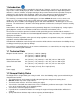
4.1 Model and Serial Location 1. The plate is affixed on the right side in the engine compartment. 2. Stated on the plate will be the Model and serial number, these will be needed when ordering parts. 4.2 Operator’s Area 1 – Seat, Armrests and Seat Belt 4 – Control Handles 7 – Control Panel 2 – Fuel Cap 3 – Left Fuel Tank w/ Gauge 5 – Foot Platform 6 – Deck Lift Lever and Height Adj.
4.3 Steering Control Levers The ZTO’s speed and direction are controlled by using two steering control handles. The handles can be moved forward and backward about a neutral position. Moving the control handle equal distance forward or backward the machine moves in a straight line. Left Turn Right Turn Inward Drive Position 4.4 Fuel System / Shut Off Valve The fuel shut off valve is located at the left rear behind the Off seat compartment.
4.7 Deck Lift Lever The foot operated deck lift is used to raise and lower the deck. Deck is to be in the up position when in transport, go over curbs, loading and unloading on to a truck or trailer. The ZTO has a deck lift assist spring but optional Deck Lift Foot Lever Extension Kits are available thru all Wright Dealers. (P/N 95460011) Deck Lift Lever 4.8 ROP’s A Roll Over Protection System (ROP’s, P/N 98410135) and seat belt is provided with the Wright ZTO. Do not remove the ROP’s and the seat belt.
5 OPERATING INSTRUCTIONS WARNING If you are not completely familiar with the Safety Instruction Manual read it now before proceeding with the operation of the mower. REMEMBER THERE ARE CERTAIN PRECAUTIONS LISTED IN THIS MANUAL THAT YOU MUST NOW TAKE BEFORE STARTING THE MOWER. 5.1 Inspect Mower Before Each Use Inspection of Mower: Do not use the mower if any parts are not maintained in good operating condition. Examine all moving parts prior to each use.
try moving the hand control levers, one at a time, very slightly, forward and backward. Gradually increase your speed until you are well acquainted with the operation of the hand controls and the mower’s behavior. After gaining a good feel for how the mower handles, gradually attempt higher engine speeds until familiar with operation at full throttle engine speed. 5.4 How to Stop and Park the Mower Come to a complete stop. If the blades are on, turn them off using the blade switch on the instrument panel.
5.6 Mowing on Varying Terrain See the Safety Instructions section of this manual, especially the parts on: • Initial Operating Safety Guidelines • Operation On Slopes • Operation In Reverse • Operation In Forward Direction • Operation During Zero-Radius Turns 5.7 How to Adjust Neutral Neutral refers to the mower movement when the engine is set to full throttle, control handles are moved to the inward/operate position and are in the neutral position.
After getting the mower to track straight, readjust the neutral adjustment on the pump by using a ¼” allen wrench at the Return-to-Neutral (RTN) mechanism, if necessary. It is normal to make these adjustments from time to time. 5.9 How to Test/Use the Blade Clutch/Brake Switch WARNING Before testing the blade clutch/brake operation, make sure the area is clear and there is nothing vulnerable to thrown objects from under the mower. No one should be near the mower deck or in its line of discharge.
6.2 Height-of-Cut Before adjusting the height-of-cut be sure the mower blades are off, and the rear tires have proper air pressure. Detent Pin Check for even tire wear. The height-of-cut can be adjusted the following way: • The cut height is set by allowing the foot lever to rest on a detent pin inserted into the height selection plates. To set the height of the pin, raise the mower deck to the transport height position and lock in.
6.3 Belt Tension Adjustment The pump drive belt is self-adjusting, and requires no adjustment. The blade drive belt is self-adjusting also and requires no adjustment. Replace tension idler assembly if worn or failing to maintain proper tension. 6.3.1 Replacing the Drive Belt • • • • • Stop the engine, remove the key and wait for all moving parts to stop. Remove engine to blade cutter deck belt. (Refer to “replacing the cutter deck belt” section) Raise rear the seat tray.
6.5 How to Move the Mower if the Engine Won’t Start Remove the R-clip from the neutral release arm (bypass valve). Pull arm outward and install R-clip. The control handles must be in the “In, Drive” positions to release the parking brake. (Closed) Run position 6.6 Hydraulic System (Open) Unlocked position WARNING Whenever servicing the hydraulic system, it is of the utmost importance to keep any dirt or debris from getting into the system. Clean off all parts before disassembly and assembly.
Expansion tank Expansion tank Right Transaxle Left Transaxle (b) Stationary Idler Pulley (c)Vent Plug (a) Filter Guard and Filter (a) Filter Guard and Filter 6.8 Transaxle Purging Procedure WARNING Lift the mower so that the rear wheels are off the ground. Be careful to support the mower so that it will not fall or tip while the system is bled of air. Open both bypass valves (see section 6.5). Start the machine and slowly move the control levers back and forth five or six times.
6.10 Cutting Blades WARNING In order to maintain to best cut, it is important that the blades are well sharpened and not damaged. Bent or cracked blades or blades with large nicks need to be replaced. Blades must be balanced after sharpening. To change the blades; • Stop engine, remove the key and wait for all moving parts to stop. • Engage parking brake. • Lift front of mower and secure in the raised position with jack stands. • Remove the blade bolt by turning counterclockwise.
9. If ROPS is a folding ROPS, ROPS should be in the upright position and pinned when operating the machine. 10. See General Safety Information below; This symbol means ATTENTION! YOUR SAFETY IS INVOLVED. The message that follows the symbol contains important information about safety. Carefully read the message. This Roll Over Protective Structure (ROPS) has been certified to industry and/or government standards.
6.14 Spindle and Drive Pulley Split hub R&R • • • • Remove 2, ¼” bolts from split hub and install in threaded holes in hub. Slowly tighten each bolt, alternating as you tighten bolts against the pulley. The hub will separate from the pulley. Replace grade 8 bolts and install in reverse order using the assembly holes to tighten hub onto pulley and spindle shaft. Assembly hole Threaded Removal holes Tightening will separate the hub from the pulley Assembly hole 6.
6.16 Kawasaki / Briggs & Stratton Engine Manual / Maintenance It is very important that all users of this unit read and understand the Kawasaki / Briggs & Stratton Engine Owner’s Manual. These manuals contain; safety awareness, emissions, maintenance and warranty information that is critical for the care of your engine. Below is the periodic maintenance chart directly from the Kawasaki / Briggs & Stratton Owner’s Manuals, which is included with the sale of the ZTO.
Briggs and Stratton Maintenance chart Maintenance Chart First 5 Hours Change oil Every 8 Hours or Daily Check engine oil level Clean area around muffler and controls Clean finger guard / rotating screen Every 25 Hours or Annually Clean air filter* Every 50 Hours or Annually Change engine oil Replace oil filter Check muffler and spark arrester Every 250 Hours or Annually Change air filter Annually Replace air filter Replace spark plugs Clean air cooling system* Replace fuel filter Check valve clear
7 Electrical Schematic 30
8 ZTO Consumables / Maintenance Items P/N Description 13990007 17420012 17460017 17460018 17460021 18410012 24420030 39410004 39410007 45410002 45410005 45410020 52410003 52410006 BLADE SPACER, 5/8 X 1/4 52410007 52420002 52420003 52420009 MODULE - TIME THROTTLE CABLE SWITCH, BLADE ON/OFF, RED SOLENOID RELAY, FOR MAIN HARNESS BLADE, 18" BLADE, 16 1/2" BLADE, 21" 53490019 71440001 71440002 71440003 71440008 71440009 71440010 71440011 71440012 71440013 71460065 71460067 71460070 71460085 71460096 714600
9 Decals 32
MAINTENANCE ITEM EN GI ITE NE MS SE E N BE OTE LO W FIR ST HO 8 UR S DA ILY EV ER Y HO 25 UR S EV ER Y1 HO 0 UR 0 S EV ER Y HO 200 UR S EV ER Y HO 300 UR S AN NU AL LY 10 Maintenance Interval Chart *2 Inspect for cracks in frame, cutter deck or other steel parts X X Inspect cutter deck belts for wear and alignment X Check all bolts and nuts for tightness (tighten as necessary) X Check transaxle oil reservoir level and fill as needed (use 15-50 motor oil) X Inspect drive belt, idler pulley(s) an
Maintenance Record Date Maintenance/Service Performed 34 Unit Hours Shop/Technician
WRIGHT MANUFACTURING, INC. POWER EQUIPMENT LIMITED WARRANTY THIS WARRANTY SUPERSEDES ALL PREVIOUS ON UNITS WITH A RETAIL SALES DATE ON OR AFTER 04/01/05 The WMI mower, including any defective part, must be returned to an Authorized WMI Service Dealer within the warranty period. The expense of lost production time and delivering the mower to the Authorized WMI Service Dealer for warranty work and the expense of returning it to the Owner after repair will be paid for by the Owner.
FEDERAL AND CALIFORNIA EMISSION CONTROL WARRANTY STATEMENT YOUR WARRANTY RIGHTS AND OBLIGATIONS The United States Environmental Protection Agency (EPA), California Air Resources Board (CARB) and Wright Manufacturing, Inc. (WMI) are pleased to explain the evaporative emission control system (EECS) warranty on your 2012 - 2013 commercial mower.
(2) Any warranted part that is scheduled only for regular inspection in the written instructions supplied is warranted for the warranty period stated above. Any such part repaired or replaced under warranty will be warranted for the remaining warranty period. (3) Any warranted part that is scheduled for replacement as required maintenance in the written instructions supplied is warranted for the period of time before the first scheduled replacement date for that part.
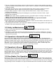
Cut Quality and Mowing Tips Problem Description Possible Cause Streaking is when strips of uncut grass are left behind. Streaking Stepped cutting is sharp ridges left in the lawn surface.
NOTES: 39
NOTES: 40
NOTES: 41
4600X Wedgewood Blvd 42 Frederick, MD 21703 www.wrightmfg.