GEAR DRIVE PISTOL GRIP Instruction Manual Wright Manufacturing 4600X Wedgewood Blvd Frederick, Md 21703 Velke PG serial 54956 and higher WARNING: READ THIS MANUAL BEFORE USING 01/2012 1
Foreword Welcome to the progressive group of mowing professionals who use Wright mowers. We are focused on giving you advanced engineering and quality construction in each mower we build. This manual explains the features and promotes safer use of the mower. Please read it and follow the instructions carefully so you can have many years of productive mowing. For service, remember that your Wright dealer knows your mower best and is interested in your satisfaction.
Table of Contents PRE-DELIVERY SERVICE OF MOWER BY DEALER ...................................................................................................................................... 4 1 INTRODUCTION .......................................................................................................................................................................... 6 1.1 TECHNICAL DATA ..............................................................................................................
PRE-DELIVERY SERVICE OF MOWER BY DEALER WARNING Before proceeding with the Pre-Delivery Service of your mower, please read the safety instructions manual in its entirety. Only your authorized Wright dealer should perform the Pre-Delivery Service of the mower. The Wright Velke Gear Drive Pistol Grip is shipped completely assembled and has been adjusted and tested at the factory.
Drive the mower around on a level parking lot. Check that the mower drives in a straight line when both hand controls are at the full speed position. (If not, refer to How to Perform The Tracking Adjustment section of this manual) As you drive the mower, listen for any unusual noises and test for irregular operation and adjust or service as necessary. Go over the safety information and operating procedures in this manual with the customer.
1 Introduction This mower is built to the highest standards in the industry. However, carelessness or operator error may result in serious bodily injury or death. Accident and hazard prevention are dependent upon the awareness, concern, wisdom, and proper training of the personnel involve in the operation, transport, maintenance, and storage of the equipment. Make sure every operator is properly trained and thoroughly familiar with all of the information in this manual before operating the equipment.
1.2.
potential users in the safe operation of this equipment and be sure they read and follow the instructions in this safety manual and other material provided by Wright Manufacturing, Inc. before using or allowing others to operate the equipment. DO NOT operate this unit unless you carefully read, understand and follow the operation and safety instructions contained in this manual and the warning decals provided on the unit.
1.10 Work Area Conditions and Inspection WARNING Prior to operating the unit, carefully inspect all lawn/ground areas where you plan to use the mower for hidden, hard-to-see objects or uneven ground that may be hidden in the grass. Clear the work area of moveable objects such as wires, rocks, glass, toys, etc. that might be picked up by the mower and dangerously thrown.
• Clean grass, leaves and lubricant spills from surfaces after use to prevent fire hazard. • Be alert for traffic when crossing roads or operating near roadways. • Before climbing curbs, crossing gravel drives, sidewalks or roads, turn off the blades and wait for them to stop. 1.12 Safety for Maintenance WARNING • Repairs carried out by untrained or unauthorized personnel may result in personal injury or serious malfunction of the Velke Gear Drive PG.
The Wright mower is capable of greater traction on slopes than typical riding mowers because of the benefits of a lower center of gravity. It is essential for you to know more about the handling characteristics of the mower so that you can enjoy more efficient mowing techniques and for increasing your safety. The Wright mower handles differently at different angles of attack on a slope.
1.18 Using a Spark Arrester The engine in this machine is not equipped with a spark arrester muffler. It is in violation of California Public Resources Code Section 4442 to use or operate the engine on or near any forestcovered, brush-covered, or grass covered land unless the exhaust system is equipped with a spark arrester meeting any applicable local or state laws. Other states or federal area may have similar laws. 1.
2 Warning, Safety and Instructional Decals • Specific safety warning decals are located on the equipment near immediate areas of potential hazards. • Keep all safety signs legible. Remove all grease, dirt and debris from safety signs and instructional decals. • Replace worn, damaged or missing safety decals. • If an attachment or accessory has been installed, make sure current safety decals are visible. 1. Throttle, Slow/Idle 2. Throttle, Fast/Full 3. Blade Engage/Disengage switch 4.
Safety Interlock System • Operator must be holding down OPC paddles to engage the PTO or the engine will stop. Drive System • Peerless 5-Speed w/ Reverse • Belt Drive Torque Specifications Thread Torque Range (ft-lbs) Locker Loctite Clutch to engine shaft 50-55 / 68-75 Nm 2760 Split Hub (Spindle & Drive) N/A 13-17 / 18-23 Nm (Gr 8) Application Blade Bolts N/A 70-80 / 95-108 Nm 32" Velke Gear Drive PG Width, deflector down 43.5" Width, deflector up 33.
4 Machine Description & Overview The Wright Velke Hydro Pistol Grip is meant to solely cut, bag or mulch grass. The use for any other purpose is not recommended. Do not disconnect any safety switches or remove any decals. 1. Drive Tire 3. Control Linkage 5. Handle-Bar Grip 7. Fuel Tank 9. Muffler & Heatsheild 11. Front Caster Tire 13. Chute Deflector 2. Drive Belt and Pulley 4. Control Handle 6. OPC Paddles 8. Engine 10. Deck/Pulley Cover 12.
4.1 Operator’s Area 1. Steering / Brake Lever 2. Neutral Latch Lock 3. Dash Panel 4. OPC Paddle 5. Velke Sulky Lock 6. 5 Speed Transmission 7. Velke Sulky Mounting Point 8. Transmission Shift Arm 4 3 2 5 1 6 8 7 4.2 Model & Serial Location 1.The plate is affixed to the top right side of the engine deck. 2.Stated on the plate will be the model and serial number, these will be needed when ordering parts.
4.3 Control Panel & Steering Control Levers The Velke Gear Drive Pistol Grip speed and direction are controlled by releasing and squeezing the steering brake levers. The OPC paddles must be held down while releasing both neutral latches. Slowly release the levers to travel forward. Use the Shifting Arm to adjust speed. 1. OPC Paddle 2. Steering / Brake Lever 3. Neutral Latch Lock 4. Choke 5. Throttle 6. PTO Switch 7. Key Switch 8. Velke Sulky Release 3 4 8 6 1 5 7 2 4.
5 Operating Instructions WARNING If you are not completely familiar with the Safety Instruction Manual, read it now before proceeding with the operation of the mower. REMEMBER THERE ARE CERTAIN PRECAUTIONS LISTED IN THIS MANUAL THAT YOU MUST NOW TAKE BEFORE STARTING THE MOWER. 5.1 Inspect Mower Before Each Use Do not use the mower if any parts are not maintained in good operating condition. Examine all moving parts prior to each use.
5.3 How to Stop and Park the Mower WARNING To stop the mower, squeeze on both hand-levers. This acts to both disconnect the wheels from the transmission and also to engage the disc brakes. Come to a complete stop. Make sure the steering brake levers are in the neutral position with the neutral latches engaged with the levers. If the blades are on, turn them off using the switch on the instrument panel.
5.8 How to Test/Use the Blade Clutch/Brake Switch Before testing the blade clutch/brake operation, make sure the area is clear and there is nothing vulnerable to thrown objects from under the mower. No one should be near the mower deck or in its line of discharge. The discharge chute deflector should be in the down position. Move the engine throttle to the highest RPM speed setting. (When mowing, the engine speed should always be at its highest setting.
6 Service and Adjustments 6.1 Tire Maintenance and Pressure WARNING Excessively worn tire tread is dangerous on all hills. Replace drive tires with less than 3/32” of any tread groove left. Use tires with the tread pattern recommended by Wright Mfg., Inc. only. Keep the tire pressure at the proper level. Higher pressures will cause the tires to have less traction which will force you to go slower, with less safety and give you a harder ride.
6.2.2 Replacing the Cutter Deck Belts •Stop the engine, remove the key and wait for all moving parts to stop. •Lower deck to the lowest setting. •Remove the deck covers. •Remove the belt by using a ½” ratchet and extension to relieve the belt tension. •Reinstall in reverse order. Figure shows belt routing and spring compression direction. 6.3 Lubrication Grease with No. 2 general purpose lithium base or molybdenum base grease. •Set parking brake, stop the engine and remove the key.
6.4 Cutting Blades In order to maintain the best cut, it is important that the blades are well sharpened and not damaged. Bent or cracked blades or blades with large nicks need to be replaced. Blades must be balanced after sharpening. To change the blades: 1.Stop engine, remove the key and wait for all moving parts to stop. 2.Engage the parking brake. 3.Lift the front of the mower and secure in the raised position with jack stands. 4.Remove the deck cover. 5.
a.This should be done with two shims (or spacers) on the bottom and one shim on the top of the caster support arm. b.The front-to-rear leveling of the blades should be between level and .25” lower (preferred) at the front of the blades but never higher at the front. •Temporary Height-of-Cut Adjustment: Using the caster shims (or spacers) you can adjust the blades downward temporarily .5” or 1” below the original coarse setting as described above.
6.11 Fuel Evaporation System All Wright Velke’s need to have this mandatory feature. • Do Not alter or remove. • Do Not fill past the “Max Fill Level” line shown in Figure. • Over-filling could result in clogging the roll-over vent and/or contaminating the purge canister. • The vapor canister is located under the dash. • Inspect and clean dust filter every 500 hrs or annually.
6.12 Kawasaki Engine Manual / Maintenance It is very important that all users of this unit read and understand the Kawasaki Engine Owner’s Manual. This manual contains; safety awareness, emissions, maintenance and warranty information that is critical for the care of your Kawasaki engine. Below is the periodic maintenance chart directly from the Kawasaki Owner’s Manual, which is included with the sale of the Velke.
7 Electrical Schematic 27
Inspect for cracks in frame, cutter deck or other steel parts Inspect all belts for wear, adjustment and alignment Check all bolts and nuts for tightness (tighten as necessary) Lubricate hand control lever pivot shafts with waterproof grease Check hydraulic oil reservoir level and fill as needed - Use SYNTHETIC oil - Mobil1 15W-50 Grease caster wheel bearings Check tire pressure; Rear tires 18-22 psi.
Maintenance Record Date Maintenance/Service Performed 29 Unit Hours Shop/Technician
WRIGHT MANUFACTURING, INC. POWER EQUIPMENT LIMITED WARRANTY THIS WARRANTY SUPERSEDES ALL PREVIOUS ON UNITS WITH A RETAIL SALES DATE ON OR AFTER 04/01/05 This WMI mower, including any defective part, must be returned to an Authorized WMI Service Dealer within the warranty period. The expense of lost production time and delivering the mower to the Authorized WMI Service Dealer for warranty work and the expense of returning it to the Owner after repair will be paid for by the Owner.
FEDERAL AND CALIFORNIA EMISSION CONTROL WARRANTY STATEMENT YOUR WARRANTY RIGHTS AND OBLIGATIONS The United States Environmental Protection Agency (EPA), California Air Resources Board (CARB) and Wright Manufacturing, Inc. (WMI) are pleased to explain the evaporative emission control system (EECS) warranty on your 2012 - 2013 commercial mower.
(3) Any warranted part that is scheduled for replacement as required maintenance in the written instructions supplied is warranted for the period of time before the first scheduled replacement date for that part. If the part fails before the first scheduled replacement, the part will be repaired or replaced by WMI according to subsection (4) below. Any such part repaired or replaced under warranty will be warranted for the remainder of the period prior to the first scheduled replacement point for the part.
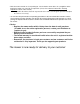
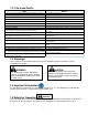
Cut Quality and Mowing Tips Problem Description Possible Cause Streaking is when strips of uncut grass are left behind. Streaking Stepped cutting is sharp ridges left in the lawn surface.
NOTES: 34
NOTES: 35
4600X Wedgewood Blvd Frederick, MD 21703 www.wrightmfg.