Instruction Manual Wright Manufacturing 4600X Wedgewood Blvd Frederick, Md 21703 Large Frame Stander Serial 54956 and Higher WARNING: READ THIS MANUAL BEFORE USING For your safety and for proper operation and maintenance read carefully and keep readily available for future reference.
Foreword Welcome to the progressive group of mowing professionals who use Wright mowers. We are focused on giving you advanced engineering and quality construction in each mower we build. This manual explains the features and promotes safer use of the mower. Please read it in its entirety and follow the instructions carefully so that you can have many years of safe and productive operation with your Wright product. This manual may contain information pertaining to European models also.
TABLE OF CONTENTS PRE DELIVERY SERVICE OF MOWER BY DEALER ............................................................................................................................................................................................... 3 1 INTRODUCTION.....................................................................................................................................................................................................................................................
PRE-DELIVERY SERVICE OF MOWER BY DEALER WARNING Before proceeding with the Pre-Delivery Service of your mower, please read the safety instructions manual in its entirety. Only your authorized Wright dealer should perform the Pre-Delivery Service of the mower. The Wright Stander is shipped completely assembled and has been adjusted and tested at the factory.
Turn on the blade clutch switch. Run blades for approximately one minute. Next, engage and disengage the blades a few times about 10 seconds apart. If the blades do not start and stop in a few seconds each time, service the blade brake system. With the blades on, disengage the OPC switch to test the Operator Presence Control switch (OPC). A time delay has been added to the OPC system. The engine should die and the blades should stop with-in 6-9 seconds after stepping off of the foot platform.
1. Introduction This mower is built to the highest standards in the industry. However, carelessness or operator error may result in serious bodily injury or death. Accident and hazard prevention are dependent upon the awareness, concern, wisdom, and proper training of the personnel involved in the operation, transport, maintenance, and storage of the equipment. Make sure every operator is properly trained and thoroughly familiar with all of the information in this manual before operating the equipment.
1.2 General Safety Instructions The Wright Stander is designed with your safety in mind. It has the following safety systems with which you should become familiar: • The warning decals on the mower including the instrument panel warning • DO NOT disable any of the safety features.
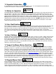
1.3 Important Information It is vital that these instructions are available to machine users. It is also important to retain with the machine if the machine is sold or transferred to another user. WARNING 1.4 Safety for Operation The Wright Stander should only be used by fully trained operators to prevent the risk of injury to themselves or other personnel.
the equipment is in safe working condition. Check the blade mounting bolts for proper tightness every eight (8) hours of operation. Check the blades for excessive wear and sharpness every four to eight (4-8) hours of operation. Sharpen dull blades. Replace blades when they become excessively worn. The mower should not be used after the blades or other part of the mower strikes a foreign object, until conducting a thorough inspection and any damage is repaired.
• The grass discharge chute deflector must be installed at all times and in the down position except that it may be raised when cleaning out the deck or a grass catcher is installed or a mulch kit and block-off plate is properly installed. • If the mower discharges grass clogs, turn off the blade clutch switch, apply the parking brake, stop the engine and remove the key before removing obstruction(s).
suddenly sliding sideways or down the hill. When operating on a slope, travel across the grade whenever possible, not in an up or down pattern. Reduce speed and exercise extreme caution on slopes and in sharp turns to prevent tipping or loss of control. Be especially cautious when changing direction on slopes. When pointing up a slope, your mower has the most weight on the drive wheels and therefore the most traction at the tires.
1.17 Using a Spark Arrester The engine in this machine is not equipped with a spark arrester muffler. It is in violation of California Public Resources Code Section 4442 to use or operate the engine on or near any forest-covered, brush-covered, or grass covered land unless the exhaust system is equipped with a spark arrester meeting any applicable local or state laws. Other states or federal area may have similar laws. 1.
2 Warning, Safety and Instructional Decals • • • • Specific safety warning decals are located on the equipment near immediate areas of potential hazards. Keep all safety signs legible. Remove all grease, dirt and debris from safety signs and instructional decals. Replace worn, damaged or missing safety decals. If an attachment or accessory has been installed, make sure current safety decals are visible. 1. Blade engage/disengage switch 3. Ignition switch, Run 2. Ignition switch, Off 4.
Fuel System • Capacity: 5.6 Gal. (L) • Type of Fuel: Unleaded regular gasoline, minimum 85 octane. Do not use gasoline containing more than 10% ethanol. Do not mix oil with gasoline. • Fuel Filter: In line • Fuel shut off: On, Off located on fuel tank Safety Interlock System • PTO switch must be disengaged, brake engaged and the control handles in the neutral and locked position to start the engine. • Operator must have feet on the platform to engage the PTO and brake off or engine will stop.
4 Machine Description & Overview The Wright Stander is meant to solely cut, bag or mulch grass. The use for any other purpose is not recommended. Do not disconnect any safety switches or remove any decals. 1. Flexible Chute Deflector 4. Hinged Upright Pad 7. Brake Handle 10. Muffler 13. Aero-Core Cutter Deck 2. Rear Drive Tire 5. Control Handles 8. Battery Box 11. Caster Tire 14. Deck Covers 3. Fuel Tank 6. Stationary Handlebar 9. Kawasaki Engine 12.
4.1 Operator’s Area 1. Anti-Tip Wheels 2. Brake Handle 3. Caster Arms/Yokes 4. Dash Panel 5. Fuel Tank 6. Upright Pad 7. Spring Loaded Foot Platform 3 2 4 5 6 7 1 4.2 Model & Serial Location 1. The plate is affixed to the rear of the engine deck in between the hydro pumps. 2. Stated on the plate will be the model and serial number, these will be needed when ordering parts.
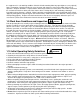
4.3 Control Panel & Steering Control Levers The Stander speed and direction are controlled by using the control handles. Moving the control handles equal distance forward or backward the machine moves in a straight line. By releasing the control handles during operation, the controls will return to the neutral position and the machine will stop. 1. Control Levers 2. Stationary Handle Bar 3. Throttle 4. Choke 5. Digital Hour Meter 6. PTO Switch 7. Ignition Switch 1 1 2 3 1 5 4 1 6 7 4.
4.6 Safety Interlock System The Wright Stander is equipped with a safety interlock system. The PTO must be disengaged, brake applied and control levers in the neutral position in order to start the machine. With the brake applied, the controls are locked in the neutral position.
5 Operating Instructions WARNING If you are not completely familiar with the Safety Instruction Manual read it now before proceeding with the operation of the mower. REMEMBER THERE ARE CERTAIN PRECAUTIONS LISTED IN THIS MANUAL THAT YOU MUST NOW TAKE BEFORE STARTING THE MOWER. 5.1 Inspect Mower Before Each Use Inspection of Mower: Do not use the mower if any parts are not maintained in good operating condition. Examine all moving parts prior to each use.
hand controls and the mower’s behavior. After gaining a good feel for how the mower handles, gradually attempt higher engine speeds until familiar with operation at full throttle engine speed. Unusual noises or irregular operation: As you drive the mower, listen for any unusual noises and test for irregular operation and adjust or service as necessary. 5.4 How to Stop and Park the Mower Come to a complete stop. If the blades are on, turn them off using the switch on the instrument panel.
5.7 How to Adjust Neutral Neutral refers to the mower movement when the engine is set to full throttle, parking brake is off, and the control levers are in the neutral position. The mower should not move forward or backward during this time. If the mower is moving forward or rearward, the neutral setting must be adjusted. The hydraulic pump has a Return-to-Neutral (RTN) device built into the linkage of the pump.
If the rod is made shorter it will increase the forward speed capability for that side of the mower and if the rod is made longer it will slow down that side of the mower. So, if the mower is tracking to the left, either the left side needs to go faster (by shortening the left-side rod) or the right side needs to go slower (by lengthening the right-side rod).
6 Service and Adjustments WARNING 6.1 Tire Maintenance and Pressure Excessively worn tire tread is dangerous on all hills. Replace drive tires with less than 3/32” of any tread groove left. Use tires with the tread pattern recommended by Wright Mfg., Inc. only. Keep the tire pressure in the drive tires between 18 and 22 psi. Higher pressures will cause the tires to have less traction, which will force you to go slower and with less safety and give you a harder ride.
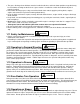
6.3.2 Replacing the Drive Belt • Stop engine and remove the key and wait for all moving parts to stop. • Remove deck covers. • Remove drive belt access panel. • Remove cutter deck engine to blade belt from clutch. • Raise front of unit and secure • Remove the clutch stop • Remove belt by using a ½” ratchet and extension to relieve belt tension. • Reinstall in reverse order. Figure shows belt configuration. NOTE: Ensure clutch stop is reinstalled.
6.4 Spring platform Adjustment The factory setting is both springs set at the most forward position. The more rearward the spring position, the stiffer the platform gets. Adjustment will be to preference of feel. The two adjustment springs should at all times, be positioned next to each other not one forward or back more than the other. To adjust, loosen each spring retaining bolt from the top just enough to slide it, then tighten with impact wrench. The nut may spin using hand wrench.
6.7 Bleeding Air from the Hydraulic System Whenever servicing the hydraulic system, it is of the utmost importance to keep any dirt or debris from getting into the system. Clean off all parts before disassembly and assembly. When any of the hydraulic parts are disconnected or removed or when the oil is changed, air must be bled from the system. If air is entrained in the system, loss of power, excessive heat, and damage to the hydraulic pumps may occur.
6.10 Battery Service The battery is 12 volts and is a maintenance free battery. Charge the battery only if it will not start the mower properly. Remove the battery from the mower before charging. Follow the instructions of the battery charger for proper and safe charging of the battery. 6.11 Fuel Evaporation System All Wright Standers need to have this mandatory feature. • Do Not alter or remove. • Do Not fill past the “Max Fill Level” line shown in Figure.
6.14 Loading and Unloading WARNING Use extreme caution when loading and unloading units on/off trailers or trucks. One full width ramp that extends beyond the rear tires is recommended rather than individual ramps for each side of the unit. The ramp should be long enough so that the angles between the ramp and the trailer or truck does not exceed 15 degrees. A steeper angle may cause the mower deck components to get caught as the unit moves from ramp to trailer or truck.
6.16 Spindle and Drive Pulley Split hub R&R • • • • Remove 2, ¼” bolts from split hub and install in threaded holes in hub. Slowly tighten each bolt, alternating as you tighten bolts against the pulley. The hub will separate from the pulley. Replace grade 8 bolts and install in reverse order using the assembly holes to tighten hub onto pulley and spindle shaft. Tightening will Threaded Assembly separate the hub Assembly Removal hole from the pulley hole holes 6.
6.18 Kawasaki Engine Manual / Maintenance It is very important that all users of this unit read and understand the Kawasaki Engine Owner’s Manual. This manual contains; safety awareness, emissions, maintenance and warranty information that is critical for the care of your Kawasaki engine. Below is the periodic maintenance chart directly from the Kawasaki Owner’s Manual, which is included with the sale of the Stander.
7 Electrical Schematic 30
8 DECALS 48 76490008 DECAL, 48” DECK SIZE 76490004 DECAL, STANDER 52 76490007 DECAL, 52” DECK SIZE 76490013 DECAL, MAIN INST. PANEL 61 76490012 DECAL, 61” DECK SIZE 76490005 DECAL, THROTTLE / INSTRUCTIONS 76490030 DECAL, CE MAIN INST.
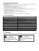
ITE MS SE EN O T BE E L FIR OW ST HO 8 UR S DA I LY EV ER Y HO 25 EV URS ER Y HO 100 UR EV S ER Y2 HO 0 UR 0 S EV ER Y HO 300 UR S AN NU AL LY 9 Maintenance Interval Chart EN GIN E MAINTENANCE ITEM *2 Inspect for cracks in frame, cutter deck or other steel parts X Inspect all belts for wear and alignment X Check all bolts and nuts for tightness (tighten as necessary) X Check hydraulic oil reservoir level and fill as needed - Use SYNTHETIC oil Mobil1 15W-50 (refer to Hydro Oil Tank Check & Fill) X
Maintenance Record Date Maintenance/Service Performed 33 Unit Hours Shop/Technician
Stander Consumables / Maintenance Items P/N Description 11990038 BOLT, HEX 5/8-11 X 9 Z5-STANDER 36/42 12990003 NUT, HEX 5/8-11 Z FOR BLADES 13990007 MACH BUSH 5/8 X 1 1/2 X 1/4 Z 13990011 WASHER, FLAT USS 5/8 Z 13990022 CASTER SPACER, NOTCHED C-TYPE 13990023 MACH BUSH, 1 1/4 ID X 1 7/8 OD X 14 GA 14990002 HBUSH SMALL, Brake Bar bushings 14990003 BUSHING, CASTER, FOR 1 1/4 PIN 15990013 LYNCH PIN 7/16 FOR CASTERS 17460007 CHUTE DEFLECTOR, RUBBER PIECE ONLY 17460012 BUMPER, RUBBER, BLAC
WRIGHT MANUFACTURING, INC. POWER EQUIPMENT LIMITED WARRANTY THIS WARRANTY SUPERSEDES ALL PREVIOUS ON UNITS WITH A RETAIL SALES DATE ON OR AFTER 04/01/05 The WMI mower, including any defective part, must be returned to an Authorized WMI Service Dealer within the warranty period. The expense of lost production time and delivering the mower to the Authorized WMI Service Dealer for warranty work and the expense of returning it to the Owner after repair will be paid for by the Owner.
FEDERAL AND CALIFORNIA EMISSION CONTROL WARRANTY STATEMENT YOUR WARRANTY RIGHTS AND OBLIGATIONS The United States Environmental Protection Agency (EPA), California Air Resources Board (CARB) and Wright Manufacturing, Inc. (WMI) are pleased to explain the evaporative emission control system (EECS) warranty on your 2012 - 2013 commercial mower.
(2) Any warranted part that is scheduled only for regular inspection in the written instructions supplied is warranted for the warranty period stated above. Any such part repaired or replaced under warranty will be warranted for the remaining warranty period. (3) Any warranted part that is scheduled for replacement as required maintenance in the written instructions supplied is warranted for the period of time before the first scheduled replacement date for that part.
Cut Quality and Mowing Tips Problem Description Possible Cause Streaking is when strips of uncut grass are left behind. Streaking Stepped cutting is sharp ridges left in the lawn surface.
Notes:
Notes:
Notes:
4600X Wedgewood Blvd Frederick, MD 21703 www.wrightmfg.