Grass Collection System OWNER’S MANUAL AND PARTS LIST For use on the Wright Z 98320007 98320008 98320009 98320010 48” 2-BAG COLLECTION SYSTEM 52” 2-BAG COLLECTION SYSTEM 52” 3-BAG COLLECTION SYSTEM 61” 3-BAG COLLECTION SYSTEM Note: Please read all safety instructions before operating your Grass Collection System. This manual also contains installation instructions and a replacement parts list for your commercial product. Please visit us on the web at www.wrightmfg.com for newer revisions of this manual.
Welcome to the progressive group of mowing professionals who use Wright commercial products. We are focused on giving you advanced engineering and quality construction in each mower we build. This manual explains the features and promotes safer use of the mower. Please read it in its entirety and follow the instructions carefully so that you can have many years of safe and productive operation with your Wright product.
TABLE OF CONTENTS Safety Instructions General Safety Removing An Obstruction Mower Stability Safety Decals Installation Instructions Before You Begin Deck Preparation and Pulley Installation Blower Installation Deck Cover Installation Rear Collection System Installation Transfer Tube Installation Optional Deck Counterweight Operation Instructions Specifications Illustrated Parts List
. This is the safety alert symbol. It is used throughout this manual and on the owner’s safety labels to alert you to potential personal injury hazards. Read these instructions carefully. It is essential that you read the instructions and safety precautions before you attempt to work on or use this unit. Obey all safety messages that follow to avoid possible destruction of property, injury or death General Safety • Become familiar with the Wright Z and it’s Owner’s Manual.
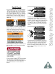
Safety Decals It is essential that you become familiar with the safety decals on your grass collection system. The safety decals will alert you of potential hazards with operating the equipment. Following these cautions will help create a safe operation and prolong the life of your equipment. The following decals are located on your equipment. Replacement decals are not available through Wright mfg. Located on blower, Always use caution with movable parts.
Before You Begin... Tools You Will Need 7/16” Wrench 1/2” Wrench 9/16 Wrench 3/4” Wrench 7/8” Wrench 13/16” Wrench Rubber Mallet Jack and two block supports Abrasive Paper Drill Safety First Use appropriate safety precautions. Warning: Rotating parts can cause serious injury. Wear eye protection and appropriate footware. Disconnect Spark Plug wires on equipment before you begin to work. Do not test blower unit until firmly attached to mower and all safety guards are in place.
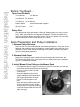
• Using a rubber mallet, gently hammer the pulley assembly onto the spindle shaft. It is necessary to maximize the engagement of the pulley and the spindle shaft. • Tighten the hub bolts with a 7/16” wrench. Alternate bolts when tightening to maintain a balanced load on each bolt. Blower Installation 1. Mounting the Blower to the Deck Lift the blower and insert the front tab of the bracket into the mating hole on the deck-top bracket.
Install New Deck Cover For 48” Mower Deck 1. Place offset stud adapter on existing deck cover stud. 2. Secure in place with the supplied 3/8” flange nut. Do not tighten completely. 3. Place deck cover on mower deck and verify the correct stud location. Remove Cover and tighten nut. 4. Place another 3/8” nut on the stud adapter and adjust location to properly support deck cover when installed. 5. Place new deck cover on mower deck and tighten deck knob. For 52” Mower Deck 1.
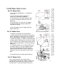
Rear Collection System Installation 1. Attach Muffler Tail Pipe and Clamp • The tail pipe must be installed to direct the exhaust away from the bags on the rear collection system. Slide end onto existing muffler exhaust pipe. Orient the tail pipe so that it directs the exhaust to the right side of the mower. This will prevent excess heat exposure to the grass collection bags. • Use enclosed screw to secure the tail pipe to the muffler. 2.
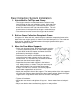
4. Mount Collection Hood Frame to Mower Frame and Assemble • For 52” Triple Bag Units: It is necessary to use the offset adapter for mounting. This improves the access of the trim edge on the left side of the mower. Attach using 4 3/8” bolts and nuts on each adapter bracket. Use the attached pins to secure the rear assembly to the mower. For all other units: Mount to tube slots located on the upper rail of the rear face of the hood frame. Use the attached pins to secure the rear assembly to the mower.
Before You Begin… • Clear lawn of all debris, including exposed rocks, fallen limbs and sticks. • Clean underside of deck and grass collection system to make sure it is free from clogs, grass buildup, or any other obstructions. • Check moisture content of grass before mowing: if the grass is wet, it will likely clog easily. Additionally, collecting long cuts of grass can also clog easily.
48” Twin Receptacle 52” Twin Receptacle 52” Triple Receptacle 61” Triple Receptacle 48” 52” 52” 61” 2 2 3 3 Bag Material Polyester w/ Polyethylen e bottom Polyester w/ Polyethylen e bottom Polyester w/ Polyethylen e bottom Polyester w/ Polyethylen e bottom Bag Size (WxWxH) (in.) 18”x18”x24” 18”x18”x24” 18”x18”x24” 18”x18”x24” Total Capacity (Bushels) 8 8 12 12 Rear weight empty (lbs.) 108 108 140 140 Rear weight full (lbs.
GRASS COLLECTION SYSTEM PARTS LIST REF # PART NUMBER DESCRIPTION 1 2 4 5 6 9 10 11 12 13 14 15 16 17 18 19 SEE BELOW 51410024 98330002 98320033 98320026 98330003 93460095 93460096 98320023 12990022 98320046 98320024 12990021 SEE BELOW SEE BELOW 98320052 98320090 98320089 98320091 93460091 71460008 11990090 98320047 98320087 98320092 98320013 93460099 98320014 93460098 98320022 BLOWER ASSEMBLY TAIL PIPE BLOWER MOUNT BOLT, FLANGE 3/8"-16 X 3/4 Z5 NUT, LOCK FLANGE 3/8"-16 GRASS COLLECTION RECEPTACLE FRAME
BLOWER PARTS LIST REF # PART NUMBER DESCRIPTION QTY.
2-BAG CATCHER PARTS LIST REF # PART NUMBER DESCRIPTION QTY.
2-BAG CATCHER 20 19 29 28 18 24 5 4 11 15 4 6 2 10 8 10 16 14 18 19 20 13 8 17 9 23 27 25 1 22 9 7 12 6 26 3 10 17 33 21 32 10 31 1 8 30
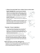
3-BAG CATCHER PARTS LIST REF. # PART NUMBER DESCRIPTION QTY. 1 2 3 4 5 6 7 8 9 10 11 12 13 14 15 16 17 18 19 20 21 22 23 24 25 26 27 28 29 30 31 32 33 98320058 3-BAG SUPPORT MOUNT 3-BAG CAP SUPPORT AIR DOME FRAME (3-BAG) CATCHER BAG, COMMERICAL CLAMP BRACKET, 2-3 BAG CATCHER Gas Cylinder Mount HANDLE, BAG 3 -BAG DEFLECTOR 1.5" HOLE PLUG, PLASTIC 1/2 DETENT PIN 2.5" LONG GAS SPRING BALL JOINT 5/16-18 Nylon Insert Nut 1/4" USS WASHER LOCKWASHER 1/4" MEDIUM SPRING CAP SCREW 1/4-20 x .
3-BAG CATCHER 15 28 14 13 5 3 9 18 16 2 12 16 12 17 21 11 10 8 21 22 29 13 14 25 32 12 19 30 1 6 31 15 17 23 22 7 20 4 33 27 11 26 12 21 12 1 24
4600X Wedgewood Blvd Frederick, MD 21703 www.wrightmfg.