
User Manual


13
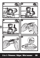
3 in 1: Trimmer / Edger / Mini mower
EN
ASSEMBLY & OPERATION
Action Figure
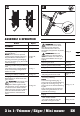
ASSEMBLY
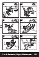
Assembling the Safety Guard See Fig. A1, A2
Mounting the Edger /Trimming
Support Wheels
NOTE: There are three optional
positions for the Edger /Trimming
Support Wheels to attach when
assisting in Trimming and Edging.
Fig. B1 is for Edging. Fig. B2 and B3
is for Trimming.
See Fig. B1,
B2, B3
Installing and Removing the Battery
Pack
Your Battery Pack is UNCHARGED
and it must be fully charged once
before it is used.
See Fig. C
Checking the Battery Condition See Fig. D1
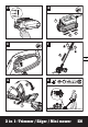
Charging the Battery Pack
More details can be found in char-
ger’s manual
WARNING! The charger and
battery pack are specially
designed to work together so do
not attempt to use any other devic-
es. Never insert or allow metallic
objects into your charger or battery
pack connections because of an
electrical failure and hazard will
occur.
See Fig. D2
1
2
O2 O3
O1
N1 N2
N3
O4 P
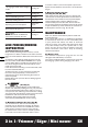
OPERATION
Safety ON/OFF Switch
WARNING! The cutting
head continues to rotate
after the trimmer has been
switched off; wait until it has
completely stopped then lay down
the tool.
WARNING!Make sure
that line is fed out before
operation. Make sure motor is up
to full speed before trimming or
edging.
See Fig. E
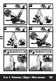
Adjusting the Shaft See Fig. F
Adjusting the Auxiliary handle See Fig. G
Using the Flower Guard See Fig. H
Trimming
- Adjusting the Trimmer Head
See Fig. I1, I2,
I3, I4
- Trimming / Mowing
NOTE:
● For trimming/mowing Fig. J1,
please mount the wheels following
Fig. B3. For trimming in Fig. J2,
please mount the wheels following
Fig. B2.
● You could also use the machine
without the guide wheels on the
guard when trimming.
See Fig. J1, J2
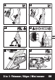
Edging
- Main handle rotation
- The main handle can only be
adjusted at 2 angles of ±90°.
See Fig. K1, K2