This equipment has been tested and found to comply with the limits for a Class A digital device, pursuant to Part 15 of the FCC Rules. These limits are designed to provide reasonable protection against harmful interference in a residential installation. This equipment generates, uses and can radiate radio frequency energy and, if not installed and used in accordance with the instructions, may cause harmful interference to radio communications.
Table of Contents Introduction..............................................................................................................................................................4 Differences...............................................................................................................................................................4 Installation..........................................................................................................................................
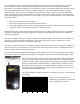
Introduction The 7001 RF Terminal is a low cost, easy-to-use radio frequency interactive terminal which communicates with PCs (or any computer) by RS-232 serial port. This new terminal offers unprecedented power and ease of use, while maintaining compatibility with programs written for the older Worth Data Terminals. The list of fantastic features include: • Low Cost • Up to 3.
• Speaker volume is controlled by the RF Terminal's Setup menu. • The 7000 Series does not have a choice of battery types. It comes with a built-in Li-Ion rechargeable battery. The battery is charged by the same power supply that is used with the Base Station. An adapter cable is provided to allow connection to the RF Terminal. • Voice prompts are now recorded on the PC and uploaded to the RF Terminal using the Voice Prompt utility.
Installation Components The components in your R/F Terminal system will vary according to the configuration of your system. Your R/F Terminal shipment should contain at least: • An RF Terminal T7001 or LT7001 - If the R/F Terminal is an LT7001 model, it will have an integrated laser scanner built-in to the body of the terminal. • Serial Cable – for programming and voice prompt upload. • 5V Power Supply – battery charger with adapter cable.
out to the serial port, which then passes this data on to the Base station. The Base station then broadcasts the message to the terminal, causing the terminal to display the message to the user. The Base station is not machine-sensitive (it needs a standard RS-232 serial port) nor is it operating system dependent (you just need to be able to read and write to the serial port as a separate device).
R/F Terminal Operation Using the RF Terminal keypad… The R/F Terminal is turned on by pressing the green ON/OFF button located in the upper lefthand corner of the R/F Terminal keypad. It is a good idea to fully charge the R/F Terminal before you use it the first time to make sure the battery charged. See below for more information on battery charging.
be significantly shorter than when the device was new, the battery should be replaced. If you have the optional “gun” handle with the extended battery then both batteries should be replaced at the same time. The main battery is a common digital camera battery sold as Fujifilm NP-120 or Pentax D-LI7. We use a high quality Japanese Li-Ion cell in our OEM pack that we supply with the R/F Terminal. You can obtain a replacement from Worth Data (P/N: L02) .
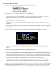
R/F Terminal Menu Functions Upon power-up, the R/F Terminal displays the following opening screen: R/F TERMINAL LT7001 FIRMWARE: Uxxx – HWyy-Rzz USA CHANNEL: 0 TERM ID: 0 HIT ANY KEY TO CONTINUE (The opening screen can be bypassed upon power up. See Chapter 2) • On second line on the screen, FIRMWARE: Uxxx, gives the firmware revision number. The letter U indicates USA frequency. Rzz refers to the version of the radio processor firmware. • HWyy indicates the version of the hardware.
step. You can use the F1 key to exit and SIGN OUT when using a Two-Way communication program running on the host computer. The entire mode menu can be skipped (see Chapter 2; RF System Setup), causing the R/F Terminal to automatically SIGN-ON or go to ONE-WAY mode on power up. Installing the RF Terminal Utilities Software The RF Terminal system ships with a CD of programs for use with the RF Terminal and Base station.
• • • R/F TERMINAL EPROM LOADER HELP R/F TERMINAL EPROM LOADER UNINSTALL See Appendix D; Firmware Upgrades for details on how to use the EPROM Loader programs (Windows).
RF System Setup The RF Terminal can be configured using the Terminal Setup Menu. Most users do not need to change anything in the setup. The most commonly changed setup parameters are the Terminal ID (especially if you have more than 1 terminal) and the Channel (if you are adding an additional Base station).
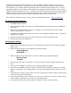
SPEAKER SETTINGS LASER SETTINGS LCD SETTINGS OTHER SETTINGS SYSTEM TOOLS DONE/EXIT 5 6 7 8 9 0 Select the option you want to set or verify or press 0 or the F1 key to exit back to the MODE MENU.
ID, select option 2 on the keypad after which a box will appear where you can enter the desired Terminal ID. Enter one character for the Terminal ID. RF Terminal Channel Default Channel 0 • The terminal's radio operates by "frequency hopping" spread spectrum. The radios hop from one frequency to another using a pseudo-random sequence. The radio goes through 26 different frequencies and then repeats the sequence – all in the 902-928 MHz band at 250 milliwatts of power.
• Several special keys on the RF Terminal keypad can generate a response automatically, sending a separate message to the host by simply pressing the appropriate control key (without pressing the ENTER key afterward). This allows for simple and fast scrolling by the operator. The arrow keys, Begin, End, and Search are the specific keys supported. The default setting is to require the ENTER key to be pressed before data transmission.
• Enabling use of the Mod 43 check character requires that the last character of your bar code conform to the Mod 43 check character specifications. See Appendix E; Code 39 for more information. Enable transmission (6) will send the check digit data along with the rest of the bar code data to your computer. To use 6, you must also be using 5. • Caps Lock ON causes lower case letters read as data to be transmitted to the computer as UPPER CASE, and upper case letters to be transmitted as LOWER CASE.
UPC-E / EAN-8 Options UPC-E First Digit EAN-8 First Digit UPC-E Check Digit EAN-8 Check Digit UPC-E Expanded UPC-E1 ON ON ON ON ON ON OFF OFF OFF OFF OFF OFF 1 2 3 4 5 6 • Use setting 1 and 2 to enable or disable the UPC-E or EAN-8 first digit. • Use setting 3 and 4 to enable or disable the UPC-E or EAN-8 check digit. The check digit is the last character and is based upon a calculation performed on the other characters. • Use setting 5 to select UPC-E0 compressed or expanded.
the bar code data to the computer. • 2 of 5 is so susceptible to misreads that the RF Terminal adds an additional safeguard - it can be configured to look for fixed-length data only. • The default setting of 06 causes the RF Terminal to read only 2 of 5 codes that are 6 digits in length. To set the RF Terminal to read a different length, enter any two-digit number. 2 of 5 code must always be an even number of digits so the length setting must always be an even number.
Other Bar Code Options Storage Tek Label Labelcode 5 Labelcode 4 Bar Code ID's ON ON ON ON OFF OFF OFF OFF 2 3 4 5 The Storage Tek Tape Label code is a proprietary variation of Code 39 code used for the storage of computer data tapes. Enabling the tape label code does not disable reading of Code 128 or Code 39 bar codes. Labelcode 5 and Labelcode 4 are proprietary bar code types used by Follet. Bar Code ID’s are characters assigned to each bar code type to identify that particular type of code.
your serial Printer supports it. It DOES NOT apply to the Cameo and QL3 Printers. • Settings E and F pertain to the way the RF Terminal handles illegal statements coming from the host computer. RF Terminal software versions prior to 9.059 did not handle illegal statements the same way as current versions. This setting is really only applicable if you had written your host program to be compatible with RF Terminal versions prior to RFT9059.
Speaker Settings Speaker Options Beep Volume OFF Low Medium High 1 1 1 1 The default volume of the “Beep” is Medium. Each time you press the “1” key you will hear a beep at the different volume settings. When you are happy with the loudness of the beep tone, press 0 or F1 to exit. Beep Tone 1 - Lowest 2 - Low 3 - Medium 4 - High 5 - Highest 2 2 2 2 2 The default beep tone is 3 – Medium. Each time you press the “2” key you will hear a beep at various tones.
to try and read a code. This option is useful for trying to read poor quality code. The default beam time is 2 seconds. Aiming Dot Duration Aiming Dot Duration (in 1/10 seconds) 00 – 99 3 • This parameter applies to the built-in internal laser. Before the laser beam spreads, you can create a brighter aiming dot to be sure you are on the bar code you want to read. The default is set to 00, no aiming dot. You can key in 01 through 99 which creates an aiming dot in 1/10th second increments; i.e.
Other Settings Preamble Preambles are user-defined data that is attached to the beginning of data (bar code or keyed) that is transmitted to the host by the RF Terminal. For example, if you set a preamble of @@ and scanned bar code data of 12345, @@12345 would be transmitted to the host. By default, the RF Terminal has no preambles configured. Preambles can contain up to 15 characters entered from the keypad or scanned from the bar coded FULL ASCII Menu.
lengths, no decode will result. Entering data by keypad is not affected. Postamble Postambles are user-defined data that is attached to the end of data (bar code or keyed) that is transmitted to the host by the RF Terminal. For example, if you set a Postamble of @@ and scanned bar code data of 12345, 12345@@ would be transmitted to the host. • By default, the RF Terminal has no Postambles configured. Postambles can contain up to 15 characters.
Characters This setting allows the RF Terminal to output chosen ASCII characters in place of the actual characters entered. For example, if you scanned the number 1 (hex 31) and wanted the RF Terminal to output hex 92 instead, you would enter 3192 for the Characters parameter. This would re-assign the output characters, with the RF Terminal outputting hex 92 every time it sees hex 31. To re-assign characters: • Select option “8” from the RF Terminal Setup menu then “3” to enable character entry.
Base and Relay Setup The Base and Relay Setup is only accessible via the RF 7000 Configuration Utility included on the Utilities CD that came with your RF Terminal. You can also download the utility from our website at: http://www.barcodehq.com/downloads.
You can enable a Security Code for either a Base or a Relay. The Security Code needs to be three characters and when enabled, requires anyone wanting to make a change to the Base or Relay to enter this 3-character code. "Xon/Xoff Sensitive" should be checked ONLY if your system has XON/XOFF specified for handshaking on the serial port in use. Typically in Windows, handshaking will be set to "None" and you should leave this setting unchecked.
the best location for the Base Station. The site survey evaluates the signal strength of a number of test packets that are exchanged between the Base and Terminal. The higher the number, the more successful your communications will be from that area. This helps you to identify problem areas before you implement your RF Terminal system. At 30 ft., this is also the acid test for suspected bad radios in a base or in a terminal.
Lets suppose that a RF Terminal and a Base Station have been processing data by sending prompts and data back and forth as described in example 1. The Base Station sends a data prompt to the RF Terminal, the RF Terminal transmits the operator-entered data back to the Base Station. If the host program has another prompt for the terminal, the Base sends it out, repeating the process above.
Mode. Once the RF Terminal transmits data to the Base Station, the Base Station acknowledges receipt of the information by echoing back the data to the Terminal that sent it, along with a beep. If the data transmission did not make it through to the Base station after 10 tries, the RF Terminal will give two long beeps and display the following message: TRANSMISSION FAILED TO RETRY, MOVE CLOSER AND PRESS ENTER. F1 TO EXIT.
Survey mode displays the success rate of sending 100 packets to the Base. The higher the number, the more successful your communications will be from that area. Site Survey does not require your Base Station be attached to your Host Computer. All you need is your Base Station, 5v power supply and RF Terminal. For detailed information on how to perform a Site Test and use the results to determine the best location for your Base Station, go to Chapter 4; Performance Issues.
• Make sure all other Base Stations are turned OFF. • Make sure that the Base Station and RF Terminal you are using are set to the same channel. Base Stations and RF Terminals are shipped from the factory set to channel 0. If you need to change the channel, see Appendix A; Channel and Jumper Changes. The Base Station does not need to be connected to a host computer to do a Site Survey. Simply connect the Base Station to wall power using the 5v power adapter.
Relay Stations Since the range of the LT7001 Terminal is quite large you probably won't need a relay unless you must have coverage in more than one location that is difficult to cover with a single base. An example of this would be inside two or more metal buildings where a base would be in one building and a relay in the other. Relays work like a remote antenna, passing data to the Base Station via cable instead of radio frequency. Base Stations are used as Relay Stations by changing the jumpers inside.
At this point, the RF Terminal puts out the “who can hear me” message. The RELAY n CANNOT BE HEARD message usually indicates a cabling problem and should be checked out immediately. Sometimes a Relay gets a response from the Base Station that is partial data or garbage. The Terminal retransmits its data since it has not received a new prompt. If this occurs ten times, the RF Terminal broadcasts, “who can hear me”. At this point the Relay is still functioning and answers the RF Terminal’s call.
The bottleneck could partially be the serial port baud rate in high volume applications. The default baud rate is 9600 baud; you can increase this up to 115,200 baud, but the greater the baud rate, the less the RS-232 cable distance allowable. The gating factor for the application is almost always going to be the application program. By splitting the application between two or more work stations, each talking to a separate set of Terminals/Base Station, that factor can be minimized.
Command without an ID All of these error conditions are detailed in the next chapter. Don’t forget to program for them; this is a common mistake. Failure to trap them will give create very strange, unpredictable results. Even though you don’t think your code will ever make a mistake, take advantage of feedback that the Base Station provides. Failure to do so is a common mistake that eventually results in serious program failure, sometimes due to hardware problems that go undetected.
Programming for the RF Terminal The four levels of programming support offered for the RF Terminal are: • Low Level ASCII sequences sent to and from the Base Station by the user program reading/writing to the serial port. • Low Level ASCII sequences sent to and from the Base Station using DLL for Windows for serial port reading/writing. • Active X drop-in components. Every necessary function is defined. You just complete the code for each function.
Here is a listing of valid commands and examples: Command characters *@ 3@ 1@Bn 2@C0 Command function Reinitializes all terminals Reinitializes Terminal #3 Make Terminal #1 beep n (1-9) times * 0@C1 1@C2 2@C3 0@C4 3@C5 * 1@C6 * 1@C71@CF 1@CX 1@CY 1@CZ 1@Dn 1@Vnn 1@Sdataxxxx Clears the entire screen (4, 6 or 15 lines) on Terminal #2. *See more about 4 and 6 line displays on page 6-4.
The color codes are: 0 = AQUA 1 = BLACK 2 = BLUE 3 = FUCHSIA 4 = GRAY 5 = GREEN 6 = LIME 7 = MAROON 8 = NAVY 9 = OLIVE A = PURPLE B = RED C = SILVER D = TEAL E = WHITE F = YELLOW Here are some examples: @CS2M2L2 will clear the screen and set the first two lines of the screen to be small fonts, the next two lines to be medium fonts, and the next two lines to be large fonts. The remaining undefined lines will be small font with the default colors.
background for all lines. The total height of the lines will be (1x16)+(3x24)+(1x32)+(1x16)+(2x32)=200 pixels: this is line 1 this is line 2 this is line 3 this is line 4 this is line 5 this is line 6 this is line 7 this is line 8 The active colors change whenever \cb is received in a prompt. The user default will be used to display all the prompts unless \cb changes the colors. All prompts will start with the user default.
For example, the command @1,1,1, Enter Quantity would display Enter Quantity starting at position 1 on line 1, then wait for the operator to enter their data.
The @S command (for serial output) statement cannot be combined with any other command - even clear (@Cx) commands. After a @S command is successfully completed, the Base Station sends back to the host the RF Terminal ID followed by a CR (ASCII 13). There is a 231 character limit on data for this command. If you send a command of more than 231 characters, you will get an Illegal Command returned, (ID ? CR).
a carriage return) back to the Host computer. • The “Clear lines” command (@Cx) for the 4 line displays differ slightly from the “Clear lines” command for the current 6 line displays.
Base Station to Host Formats The basic format of a message that is transmitted from Base to Host is fairly simple: Byte position Function Possible values 1 2+ Last RF Terminal ID Data Transmitted Termination of message 0-9, A-Z, a-z, - = ** CR (ASCII 13) Typically, the Base Station is sending the “answer” to the hosts “question” - for example, if a Base sent a host message to a terminal #2 that said: 2@1,1,1,ITEM NUMBER + EOT The RF Terminal would display ITEM NUMBER on line 1, position 1 and accordin
a valid command - remember that all messages must end with a request for data input. The host should then expect a response from the terminal of Terminal ID + DATA (none if only pressing ENTER key) + CR. SIGN ON is a good way for the terminal operator who has not received instruction from the host for several minutes to determine if he is still connected and if the host is still functioning. By SIGNing OUT and SIGNing back ON, the operator should receive a message that there is nothing to do.
Check your program for the sequence error before starting again. The host program will have to reinitialize the Base Station or you will have to cycle power on the Base Station and have the Terminal Sign On again in order to continue. Sequence Error Message The host program must observe the one-for-one "host prompt/terminal response" protocol at all times. The host cannot send a second data entry prompt until it has received a response to the first data entry prompt.
Automatic Check Back When a terminal checks back in to see if there is a change in instructions, the host can send back the same prompt or send back a new prompt. The check back occurs according to the time specified in the Terminal's setup, (specified in increments of 5 seconds).
The STATUS key is reserved to only display the Time and Date. The Control keys can be used without pressing the ENTER key by using the Control Keys Only Terminal Setup parameter. See Chapter 2; RF System Setup for details.
PromptCOM/ActiveX Drop-in components are tools that are added to your programming environment "tool kit". There are a variety of different technologies around for implementing a drop-in component such as VBX (for Visual Basic) and VCL (for Delphi and C Builder) and COM (ActiveX). Only the ActiveX variety are widely compatible with almost all development environments.
• Methods are function calls used to issue commands and access features of the drop-in component. An example of a method is sending an Input command to the terminal. • Events are function definitions placed in your application’s source code. The function definitions in your source code are called Event Handlers. The skeleton structure of the event handler’s source code is automatically generated. The code in the Event Handler is called ("fired") by the drop-in component when a specific event occurs.
ComStopBits Valid values: 1, 2 Definition: This is a serial port setting and must match the base station setting. WDterm may allow other settings but those listed here are the only ones compatible with current version base stations. Quiet Valid values: True, False Definition: If Quiet is set to True then any status and error message generated by WDterm will be suppressed. Methods – ActiveX Object Methods are commands that you issue to the WDterm control.
InputKeyBd Parameters: line, position, prompt, shifted, timestamped InputKeyBdColor (15-line terminal only) Parameters: line, position, prompt, shifted, timestamped,FG,BG Function: This instructs the ActiveTerminal to display the prompt at line and position and wait for data to be entered from the terminal keypad only. If shifted is set to “true”, the terminal will start in shifted mode. Timestamped appends a (hhmmss) prefix to the returned data.
Function: This instructs the ActiveTerminal to display the prompt at line and position and wait for data to be received through the terminal serial port. Waiting for serial input can be bypassed by pressing the enter key on the terminal which will send an empty data string to the host (fires the OnTermData event handler). OutputSerial Parameters: data Function: This instructs the ActiveTerminal to send data to the terminal’s serial port.
SendFormat (15-line terminal only) Parameters: FGcolor, BGcolor Function: Sends to the ActiveTerminal the current Format Definition as created by one or more calls to the DefineFormat method. It also sets the user-default display foreground and background colors. Must be followed by an Input method call to take effect. SendDate Parameters: line Function: This instructs the ActiveTerminal to display date and time on the specified line number. Must be followed by an "Input" method call to take effect.
Terminal ID is always passed as 0-63. A Terminal ID value of 99 indicates an error. Once you have the event handler skeletons, you can proceed to add whatever functionality you desire to each event. You must call the OpenDevice method before any events can be fired. OnTermBaseRegister Event: An attached base station has successfully powered up and communicated with the host computer via the serial connection. OnTermSignIn15 Data passed:terminal Event: A 15-line terminal has signed in.
method call before WDterm can respond to another keypress on the terminal. OnTermDownArrow Data passed:terminal Event: The down-arrow button has been pressed on a terminal. You must issue another Input method call before WDterm can respond to another keypress on the terminal. OnTermLeftArrow Data passed:terminal Event: The left-arrow button has been pressed on a terminal. You must issue another Input method call before WDterm can respond to another keypress on the terminal.
PromptNET TCP/IP Active X Controls PromptNET/ActiveX is a drop in COM component that allows programmers to easily add the ability to send prompts to and receive data from their R/F Terminal via an RF Base Station across a TCP/IP network connection. PromptNET requires a "Client" computer on a TCP/IP network (to which up to 4 serial Base Stations can be attached) and a "Server" computer visible on the network to the Client. The client computer runs the PromptNET Client Utility program as a background task.
Before making any WDIPterm method calls in your application, make sure to set the ServerOn property to "true". Test For Good Communication Implement an event handler for OnTermBaseRegister that causes a beep or displays a message when called. If communication between the host PC and the base station is good, your event handler will fire when your program is running and you power up an attached base station.
Properties - TCP/IP COM Properties are the various configuration variables used by the WDIPterm control. They are directly assignable in your application (eg. "WDIPterm.ServerOn = true") and can be set in your development environment’s object browser. Note that your development environment may show more properties for the WDIPterm control than are listed here. This is normal. You may ignore pro-perties you see listed in your development environment that are not listed here.
the end key on the terminal. A termID+CR will be sent to the host. InputYesNo Parameters: basename, channel, terminal, line, position, prompt Function: This instructs the terminal attached to client basename on channel to display the prompt at line and position and wait for a Yes (Enter key or C key) or a No (0 key or B key) from the terminal keypad. Note: C and B keys are used to facilitate keypad entry while scanning with the integrated laser.
effect. PlayVoice Parameters: basename, channel, terminal, msgnum Function: This instructs the terminal attached to client basename on channel to play voice message number msgnum. Msgnum may be a value from 1 to 99. Must be followed by an "Input" method call to take effect. ReInit Parameters: basename, channel, terminal Function: This instructs the terminal attached to client basename on channel to re-initialize. Must be followed by an "Input" method call to take effect.
Data passed:basename, channel, terminal Event: A four-line terminal has signed in on channel at client basename. Terminal ID is passed in terminal. OnTermSignOut Data passed:basename, channel, terminal Event: A terminal has signed out on channel at client basename. Terminal ID is passed in terminal. OnTermData Data passed:basename, channel, terminal, data Event: A terminal on channel at client basename has sent data in response to an Input method call.
Data passed:basename, channel, terminal Event: The BEGIN button has been pressed on a terminal. You must issue another Input method call before WDIPterm can respond to another keypress on this terminal. OnTermEndKey Data passed:basename, channel, terminal Event: The END button has been pressed on a terminal. You must issue another Input method call before WDIPterm can respond to another keypress on this terminal.
Portable Printers Cameo and QL 3 Common Information Both of these printers are stocked by Worth Data for the convenience of our users who need portable printing. These printers do not require any special protocol; they do not require the “wake-up byte” as do other printers. They do require a special cable that can be ordered from Worth Data (part #C12); cable pin-outs are available in Appendix C: Cable Pin-outs.
So, when the RF Terminal transmits the data to the host, it will be in the following format: RF Terminal ID + T1: DATA + CR or RF Terminal ID + T2: DATA + CR or RF Terminal ID +T1: DATA + T2: DATA + CR For further information, see your Printing Systems Programming Manual on the CD ROM shipped with the printer. Zebra QL 3 Printer The QL 3 Printer is used for label printing. It doesn’t have Magstripe input.
Voice Message Operations The RF Terminal’s exclusive use of voice prompts allows you to overcome problems such as literacy, language and lighting. With proper planning, voice prompting can enhance your RF Terminal application, making it faster and simpler. Voice messages are recorded using a utility program included on the Utility CD-ROM and then uploaded to the RF Terminal. Playback of a voice prompt is triggered by a prompt from the host computer.
Default Voice Messages Here are the default messages and the numbers they are recorded under: Message Recorded Message # Prompt ITEM QUANTITY #01 #02 Error messages LOW BATTERIES TRANSMISSION FAILED #98 #99
Troubleshooting General Considerations Site Test The most basic tool for troubleshooting is the Site Test at 50 feet range. (See Chapter 4 for the details on how to do a Site Test). If the Site Test fails at close range (50 feet), you have found the problem. The radio on either the Base Station or the RF Terminal is defective. A Terminal may operate poorly at a distance of less than 10 feet from the Base due to high transmitter power. Make sure to Site Test at least at 50 ft. range.
• The cable between the Base Station and host computer is bad. Try the test with extension cables removed. • The host COM port is bad or assigned to another device driver installed. Try another COM port or try another computer. • RARELY!!! The RS232 chip on the Base Station is bad. Terminal Error Messages Message Meaning – Action Required Relay n Cannot be Heard by the Base Notify Supervisor The terminal has established contact with Relay Station x.
• Two or more terminals with the same ID can generate all kinds of strange messages including those shaded above. • Two bases on the same channel are big trouble. Sometimes you get an error message and after checking, everything on the Base seems to be set OK. Drop power on the suspect Base and try signing in again. If you get the same message, there is another Base answering which should not be on the same channel. Troubleshooting specific problems I can’t communicate at all...
especially in warehouses or grocery stores with tall shelving. A Base Station mounted on the wall with the antenna parallel to the floor is the worst position. • In an unobstructed outdoor area a range of 3.3 miles or greater “line-of-sight” is possible but indoor “obstructed” range will be much less. Reflections and obstructions, depending on the density and material, can reduce the range to a few hundred feet indoors. Far better than typical WiFi systems.
I get extra characters at the beginning or end of my bar code data... • Clear the Preamble and Postamble settings. I have very poor read rates when scanning bar codes... • Carefully follow the scanning instructions in Appendix M; How to scan a bar code when reading any and all bar codes. As straightforward as scanning may seem, many people who call with a complaint about poor read rates simply aren't doing it right. • Try reading the following bar code below as an example of a known “good” bar code.
equipment in front of you and be prepared to explain your problem in detail to the Technical Support Engineer. • The Engineer may ask you to go through some troubleshooting procedures while on the telephone. This will help them determine what is wrong and what the course of action should be. Many problems can be resolved over the telephone and will not require that you return the equipment to us. If you do need to return any of the RF equipment to Worth Data, the Engineer will issue an RMA number.
Channel and Jumper Changes Opening a Base As preparation for changing the Channel on a Base Station or changing the Base to operate as a Relay, the case must be opened to expose the circuit board with the switches and jumpers. Be sure you disconnect power before opening the case. Turn your Base Station upside-down, and unscrew its single phillips head screw. If you don't completely remove the screw, you can use it as a lever to pull up on the cover.
Channel Changes To determine the current channel of a Base Station , power up the Base and watch the LED light on the front of the unit. On power UP, a Base LED will blink "channel +3" times. For example, a unit that blinks 5 times on power up is operating on channel 2. Channel 0 blinks 3 times, channel 5 blinks 8 times. Changing the Channel on a Base/Relay The Base Station and its related Relays must have their channel set to the same channel as the R/F Terminals in their network.
To add additional Relays, you must “multi-drop” them off a single bus line running from the unlabeled port on the Base station. See the section below for cabling requirements and pin-outs. It is very important to follow the pin-out directions carefully and to use the suggested cable type. The majority of problems we see are the result of incorrect wiring. Each Relay requires it’s own power supply.
Incorrect Routing for Wiring Relay Station RS422 Pin-outs The R/F Relay Stations are connected by twisted pair wire -- use Belden 1227A1, Cat 5 wire, or equivalent.
Because relay cabling is often troublesome, we supply a test cable for isolating the user-made cable from the process. This test cable is so short that it doesn’t follow the rules of twists on the previous page – it is just a Ethernet patch cable for node, but adequate for testing the relay. HINT: Use the suggested wire type, and if you’re doing your own crimping, be sure to use the expensive metal crimpers ($100) and not the cheap plastic crimpers ($15).
• If the Base is first in a string, (not in the middle or end of a string), set the 422 jumpers to Base w/RS422 termination. • The last Relay in each string should have its jumpers set as a Relay w/RS-422 termination. Any Relay that is not the last relay in the string would not be terminated. • Relay Station failures are often cable-related.
Mod 8 RJ45 1 2 3 4 Function Shell (chassis ground) Transmit Data Receive Data Signal Ground DB 9 Female Shell 2 3 5 F36 9 pin cable If you plan on building your own extension cables, you must use well shielded cable and you cannot use twisted -pair cable. You can order custom length RS-232 extension cables from Global Computer Supplies ph. 800-845-6225, part number ZCC4912X. Many other companies sell 10 ft., 25 ft., and 50 ft. DB9 Extension Cables including Radio Shack.
Terminal Utilities Disk. If you have received a disk with the latest firmware or have downloaded the firmware from our website, www.barcodehq.com, download the firmware into the RF Terminal by following the instructions on the screens of the program for a normal Terminal firmware update. Failsafe Firmware Download for a Terminal If the firmware gets completely wiped out, you will get a blank screen or a blank screen with a cursor in the upper left.
can vary from a low of .75 characters per inch (cpi) to a high of 9.4 cpi. There should be a ¼" "quiet zone" (white space) to the left and right of the bar code. Code 39 uses an asterisk (*) as a start and stop character. This character must precede and follow the data in the bar code. The RF Terminal gives you the option of transmitting or not transmitting these characters when the bar code is read.
Full ASCII Extension to Code 39 "Full-ASCII Code 39" expands the Code 39 character set to include all 128 ASCII characters. Symbols 0-9, A-Z and punctuation characters and are identical to their Code 39 representations. Lower-case letters, additional punctuation characters, and control characters are represented by sequences of two Code 39 characters.
Accumulate Mode must be turned on using the bar coded Setup Menu or by using the keypad. Accumulate Mode is located in the Code 39 parameters. Choose 4 to Enable or 5 to Disable this feature. This numeric Code 39 "Barpad" illustrates ACCUMULATE Mode. Scan 5, 3, 8, and Enter. The RF Terminal transmits a single message of “538”. 0 1 2 3 4 5 6 7 8 9 Clear Enter Code 93 Specifications Code 93 is variable length, continuous, bi-directional, compact code.
Codabar Specifications Codabar is widely used in libraries, blood banks, the cotton industry and transportation industries. Its' character set consists of numbers 0 through 9, and punctuation characters + . - / : and $. Symbols a, b, c, d, t, n, * and e are used as start and stop characters. Characters are constructed of four bars and three spaces. a12345b Codabar is a numeric-only code, but different combinations of start and stop characters can be used to identify different types of labels.
The UCC Serial Shipping Container Code specification calls for a 19 digit UCC/EAN 128 code with an additional Mod 10 Check digit (20 digits in all). The Mod 10 Check digit is calculated the same as the Interleaved 2 of 5 example in Appendix D. It is the data length as well as the MOD 10 check digit that distinguishes the UCC Serial Shipping Container Code from other UCC /EAN 128 bar codes.
Interleaved 2 of 5 Code is so susceptible to partial scans being interpreted as valid reads that we recommend at least one of the following safeguards: • Use one length of I 2 of 5 code. Using one length of data allows you to tell the RF Terminal to look for one length of I 2 of 5 code only. By default, the RF Terminal is set to look for a 6 digit I 2 of 5 code but you can set the length to something different using the RF Terminal Setup Menu.
EAN is an international superset of UPC. EAN-13 has 13 digits, with the first two digits representing a country code. The final digit is, as with UPC, a check digit. EAN-8 is a shorter version on the EAN-13 code containing seven data digits and ending again with a checksum. The exact UPC/EAN symbol specifications are available from: Uniform Code Council, Inc. 7887 Washington Village Drive, Suite 300 Dayton, OH 45459 937-435-3870 Specifications are also available via the internet at: http://www.uc-council.
check digit. For example, a bar code containing the numbers 978055337062153495 would transmit as 0553370626 in the ISBN format. The RF Terminal has the option of transmitting in the ISBN format. I S BN 0 - 553 - 37062 ISBN specifications are available from: American National Standards Institute Customer Service 11 West 42nd St. New York, NY 10036 http://web.ansi.
sixth digit: If the code ends in: UPC-E Data Insertion Digits Insertion Position 10 digit code 0 1 2 3 4 5 6 7 8 9 abcde0 abcde1 abcde2 abcde3 abcde4 abcde5 abcde6 abcde7 abcde8 abcde9 00000 10000 20000 00000 00000 0000 0000 0000 0000 0000 3 3 3 4 5 6 6 6 6 6 ab00000cde ab10000cde ab20000cde abc00000de abcd00000e abcde00005 abcde00006 abcde00007 abcde00008 abcde00009 Because the sample UPC-E code ends in a 6, the insertion digits 0000 are inserted at the sixth digit (insertion position 6): 1234500
• New Check Digit 0 • Data with check digit is: 823450 The MSI Mod 11 check digit is calculated as follows: The example bar code data is: 943457842 • Assign a checking factor to each number, starting with the units position of the number (in this example, the 2) up to the highest order position (the 9). Use checking factors of: 2,3,4,5,6,7,2,3,4,5,6,7...
To scan a bar code using your laser scanner, (whether it be a handheld or integrated) • put your RF Terminal in One-Way mode with the host computer program not running; or even unplug the serial cable, • point the laser scanner at the bar code at about 6” away. • Pull the trigger (or push the button on an integrated model) and line up the beam on the bar code. If you don’t get a read, vary the distance of the scanner from the bar code by pulling up or moving down.
ASCII Code Equivalent Table The 128 ASCII codes, their 3-digit decimal equivalents and 2-digit hex equivalents are detailed in the below table.
• The 7000 series RF Terminal does not have a choice of battery types. It comes with a built-in Li-Ion rechargeable battery. The 5000 series Base 5V power supply is now used to charge the battery on the Terminal as well. A full charge cycle takes 2-3 hours. • Voice prompts are now recorded on the PC and uploaded to the RF Terminal using a utility program provided on the Utilities CD. Up to 100 voice prompts can be stored in the Terminal with a total time of about 90 seconds.