
Instruction manual

. .
6 Input and Output 92
Step Mode
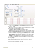
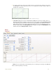
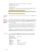
Figure 6-14: The Stimulator Step Control Panel.
A1: Starting Amplitude
A2: Stopping Amplitude.
#steps: Number of Steps
W(ms): Width of the step in milliseconds (ms)
F(Hz): Frequency of stimulation in Hertz (Hz)
#R: Repeat Count
IP Dur: Inter protocol duration
HP: Holding Potential
Apply: Applies any changes to the stimulus protocol made through the Stimulator Toolbar.
Clicking Apply while recording will send a stimulus pulse from the output
Constant Mode
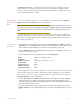
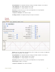
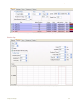
Figure 6-15: The Stimulator Constant Control Panel.
Amplitude: Amplitude.
Apply: Applies any changes to the stimulus protocol made through the Stimulator Toolbar.
Clicking Apply while recording will set the amplitude at the output.
Ramp Mode
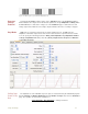
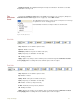
Figure 6-16: The Stimulator Step Control Panel.
A1: Starting Amplitude
A2: Stopping Amplitude
Rise time: The time taken to go from the Start Amplitude to the Stop Amplitude
Num Ramps: Number of Ramps
IR: Time between Ramps
HP: Holding potential
Apply: Applies any changes to the stimulus protocol made through the Stimulator Toolbar.
Clicking Apply while recording will send a stimulus pulse from the output
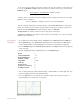
Triangle Mode
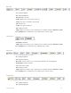
Figure 6-17: The Stimulator Step Control Panel.
A1: Starting Amplitude
A2: Stopping Amplitude