
Instruction manual

6 Input and Output 83
Holding Potential: This is a voltage between ±10V that can be programmed to shift the
resting voltage of an excitable tissue (like a nerve). It is also known as a holding voltage
because it can be used to hyperpolarize the membrane potential of an excitable tissue and
prevent it from depolarizing or “firing.”
Building Output
Protocols in Pulse
Mode
To record stimulus pulses like the examples that follow, the stimulator output of an WPI unit
can be connected to one of its own BNC inputs. On the WPI 118, this is easily accomplished by
using a BNC-BNC cable. However, the stimulator outputs of the WPI 214 unit consists of three
color-coded banana jacks, so a Double Banana-BNC adapter or cable is needed to connect two
of the banana jacks to one of the BNC inputs. To record positive pulses, connect the adapter to
the positive (red) and ground (green) banana jacks; to record negative pulses, connect the
adapter to the negative (black) and ground (green) banana jacks. Double-Banana adapters have
a flag or bump on one side that indicates which side should be attached to the ground jack.
Note: Never connect both the positive (red) and the negative (black) banana outputs of a 214 unit to its
own inputs, as this causes a short circuit that could damage the amplifier. These red and black outputs can
be connected to other devices (nerve chambers, stimulating electrodes, and more), but not to its own
inputs.
An Example of
Continuous Pulses
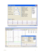
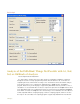
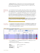
1 To construct and record some examples of stimulus pulses, select Preferences from the Edit menu. On
the Channel page of the Preferences dialog window set a channel that has a BNC input to record
at 10,000 samples/second and display 0.5 seconds on the screen. Also select the Stim1 channel and
set it to record the stimulator. (Figure 6-2 on page 83).
Figure 6-2: Channels page of the Preferences dialog window set for the pulse mode example.
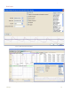
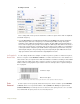
2 Go to the Stimulator page of the Preferences dialog window; select Pulses from the box in
the upper left corner of the page.
3 Enter the following values into the appropriate boxes on the Stimulator page:
Delay 100msec (an arbitrary value)
Amplitude 1V
Number of Pulses 0 (for continuous)
Pulse Width 5ms
Pulse Frequency 100 Hz