
Instruction manual

6 Input and Output 81
Chapter 6: Input and Output
Stimulator
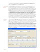
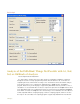
The Stimulator page in the Preferences dialog box controls the Digital-to-Analog Converter
or DAC of the WPI hardware. It can be reached by selecting Preferences from the Edit menu.
The stimulator feature sends the DAC output to the outside world. Using controls described
below, output protocols can be built from “square wave” components that are listed on the
Simulator page of the Preferences dialog window. The available output range of the stimulator
is ±5V for the WPI 214 and ±10V for WPI 118 and 3xx.
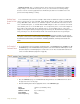
The WPI 118 has two DACs, while the 3xx has a DAC on each
channel. Each DAC can be controlled independently. The stimu-
lator drop-down box (currently set to Stim1) allows selection of
the stimulator to be setup. For devices with multiple stimulators,
the import Settings button allows the user to copy settings from
one stimulator to another.
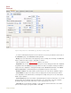
Six modes of output, Pulse, Trains, Constant (voltage), Step,
Triangle and Ramp, can be selected using the mode drop-down
box (currently set to Off). Triangle and Ramp protocols are
available only on the WPI 3xx.
The Bipolar checkbox allows the creation of bipolar pulses.
The stimulator can be set to fire when the recording is started by
checking the Start Stimulator with Recording checkbox.
Time Resolution: The WPI 3xx has three time resolutions, 0.04ms, 0.4ms and 4 ms. The finer
the time resolution the shorter the maximum time duration for each parameter. For example, at
0.04msec Time Resolution the maximum delay is 600 ms. At 0.4ms this increases to six
seconds, while at the 4msec resolution the maximum delay is 60 seconds.
The software configures itself depending on the hardware selected and will limit the available
range of values for each parameter accordingly.
Toolbar Steps: This determines the minimum step increments that the stimulator toolbar will
use when the up/down buttons on the toolbar are clicked. These are also the increments used
by sequences for programming the stimulator.