
Instruction manual

. .
5 Analysis 50
unclosed parentheses or division by zero. Since division by zero is a possible occurrence even
in legitimate expressions, but it cannot be calculated by a computer, the program substitutes the
last calculated value for the quotient if division by zero is attempted.
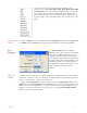
Activating
Channel Math
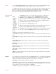
To apply the Channel Math function to a channel, click on the Add Function button in the
Channel bar. Select Channel Math from the Function menu. Select the channels corre-
sponding to A, B, C and D. Program the expression desired. Set units if desired, and click OK.
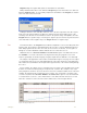
Filter Each channel has its own digital filter that can be used on-line or off-line. DataTrax2 uses a
FIR (Finite Impulse Response) filter. There are various windowing functions that can be used
for setting up an FIR filter. The Hamming window (default) is appropriate for most applications.
In addition to this windowing function DataTrax2 also provides Rectangular, Bartlett, Hanning,
Blackman and Blackman-Harris windowing functions. The filter order is the number of data
points in the raw data required to calculate each point in the filtered data. The strength of the
filter is determined by the filter order. The higher the order, the stronger the filter. Note that the
higher the order the longer it takes to calculate, which can slow down the display. Also the first
and last order/2 data points in the filtered data are invalid. For example, if the filter order is 51,
then the first 25 and the last 25 data points in the filtered data are invalid.
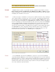
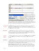
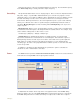
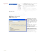
Figure 5-5: The digital (software) Filter dialog window.
In the Filter Setup dialog, drag the boundaries of the filter or enter the values in the Low
Cutoff and the High Cutoff fields to create the desired filter. The graphic interface in the Filter
Setup dialog is straight forward. The colored area corresponds to the frequencies that are
passed, and the white area corresponds to the frequencies that are rejected. To remove high
frequencies from the signal, click on the right boundary of the colored area and drag this
boundary to the left. To remove low frequencies from the signal, click on the left boundary of the
blue area and drag this boundary to the right. After clicking and dragging a boundary, it can be
placed more accurately by entering the values in the Low Cutoff and High Cutoff fields. Bound-
aries can be placed in configurations that create High Pass, Low Pass, Band Pass (as shown
in Figure 5-5 on page 50), or Notch filters.