
Instruction manual

2 Acquisition 13
For example, consider an ECG, whose total peak to peak amplitude is only 2 mV. The number
of steps that can be resolved with an 16 bit ADC is 2mV/0.600uV or a little more than three
steps, which is not sensitive enough to see any meaningful changes. If an amplifier is placed
between the signal and the analog to digital converter (ADC), the “raw” signal can be amplified
by a selected gain. For example, if the gain is 100 times (X100), the 2mV ECG signal becomes
a 200mV signal. Now, when the amplified signal is presented to the ADC, it is 100 times bigger.
The minimum signal now would represent only 1/658th of the total signal (304µV/200mV). It can
be seen that a 16-bit ADC is much more tolerant of small signals, making the gain required to
view a small signal with a 16-bit unit less critical.
Adding gain to the recording system improves the signal to noise ratio of the measuring
system, but the cost is that the ADC cannot see any signal above the +10V or below the -10V
input limits. In the case where X100 gain is applied to a 0.2V signal, the amplified signal
becomes 20V. This is above the +10V input limit of the ADC, so the signal is out of range. In
fact, the effective input range of WPI ADC units is equal to ±10V/Gain. So, if a gain of X10 is
used on an amplifier, the effective input range of the ADC drops to ±1V (±10V range/X10 gain).
Any input signal larger than 1 volts will be out of range. If a gain of X100 is applied to the input
signal, the effective input range of the ADC is restricted to ±0.1V, and so on.
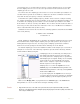
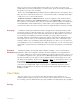
DIN 8 Inputs The DIN 8 inputs on WPI analog to digital converters can apply up to X1000 gain. This is
accomplished through the placement of a gain programming resistor within the DIN 8 connector
of the transducer or cable that can be plugged into the DIN 8 inputs of the WPI units. Gain
programming resistors are ALREADY PRESENT IN ALL WPI TRANSDUCERS. Gain
programming resistors can be installed on NON-WPI transducers by rewiring the connector.
Consult the hardware section in the appendix of this manual for the pin configurations and
diagrams of the DIN 8 connectors used with WPI ADCs.
Offset Offset is sometimes referred to as “positioning.” Some recorders, amplifiers, and transducers
have a knob that positions the baseline of the recording on the screen. Positioning control
permits the centering of the signal which makes measurements more convenient, or the lowering
of the baseline to accommodate the display of a signal that has more gain applied to it. The
availability of the AutoScale feature in the DataTrax2 software reduces the need for a
positioning knob. In fact, the very low noise of the WPI Recorders makes positioning controls
unnecessary as signals are automatically centered and expanded to fill the recording screen
when the AutoScale button is clicked. Positioning of the waveform may be accomplished by
clicking on the waveform and dragging it to the desired position within the channel.
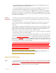
Filters Filters can be set to remove certain frequencies from signals. Hopefully, the frequency infor-
mation removed when the filters are applied is noise and not part of the signal of interest. There
are two basic types of electronic filters: Low Pass and High Pass. When used in combination
with each other, these filters can create either Band Pass or Band Reject (Notch) filters.
By definition, Low Pass filters PASS only those frequencies beLOW the set frequency. For
example: in an electrocardiogram, a large percentage of the ECG signal information is contained
in frequencies below 40Hz. A significant noise source in such recordings is the 60Hz line
voltage (110V AC power, or mains) used to power equipment and lights. A 50Hz Low Pass filter
would allow all frequencies below 50Hz (including most ECG information) to pass to the
recorder, but would exclude all frequencies above 50Hz, including the 60Hz noise from the