
Instruction manual

. .
2 Acquisition 12
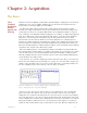
2 Open the Channels page in the Preferences dialog window and set the sampling speed to 1,000
samples per second. Record 10 seconds of data.
3 Next, set the sampling speed to 500 samples/second and record an additional 10 seconds of data.
4 Repeat this procedure for sampling speeds of 200, 100, 50, 20 and 10 samples/second.
Display a section of each recording block in the Main window, then switch to the Analysis
window. Closely examine the recorded data as displayed in the Analysis window. Notice that
the signal becomes progressively more coarse as the sampling rates go down, until eventually
the signal is unrecognizable.
Vertical
Resolution
As stated earlier in this chapter, the ADC takes measurements at regular time intervals to
produce data points with X,Y coordinates and the DataTrax2 software later plots and connects
the data points with lines.
The temporal resolution of the incoming signal was the topic of the previous section of this
chapter. In this section, the vertical (voltage) or amplitude resolution of the signal will be
discussed.
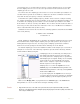
When making a measurement of length with a ruler, the accuracy of the measurement is deter-
mined by how many gradations are printed on the ruler. Clearly, a ruler with gradations every
eighth of an inch is more precise than a ruler with a gradation every inch. The more lines or
gradations there are per unit of measure, the more accurate the ruler.
If the ADC is considered to be a ruler for voltage, then its resolution (its number of gradations)
is determined by a parameter called “bit depth.”
In an 8-bit word, or byte, there are 256 (2
8
) different possibilities for the value of the byte. A 9-
bit word has twice that many possibilities (512), a 10-bit word has four times as many (1024)
and so on. LabTrax 4/16 and the WPI 118
use a 16-bit ADC providing 65,536 different possibil-
ities, while the LabTrax 24 series uses a 24-bit ADC providing for 16,777,216 possibilities. The
Digital Resolution of the ADC is the range divided by the number of possible ADC steps. This is
the minumum measurement possible with the ADC.
It is important to realize that it is not possible to make a measurement with more precision
than the Digital Resolution unless the bit depth is increased or the input range is narrowed.
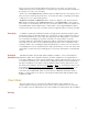
Changing the bit depth requires a different ADC to be placed in the unit. However, the input
range can be easily narrowed by applying amplification (gain) to the signal before the signal is
presented to the ADC. If a 1000X gain is applied to the incoming signal by an amplifier, the
minimum resolution of the ADC improves
Note: The actual resolution of the system depends on both the analog and the digital resolution. It is
important to always consider the resolution of the sytem as a whole.
Signal Conditioning
Gain As pointed out in the section on vertical resolution, there is a minimum voltage beneath which
the ADC cannot read. This voltage ±304µV for the WPI 118, LabTrax 4/16 and ±1.2nV for the
Labtrax 24 series. If the signal being measured is very small, additional gain can be applied to
the signal before it is presented to the ADC by using a bioamplifier.