
Instruction manual


BRIDGE8
World Precision Instruments 3
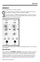
2
5
3
8
7
6
1
4
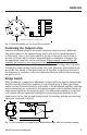
S HIELD
- 5 V
+ 5 V
+ OUT
- OUT
TRA NSDUCE R PLUG (S O LDE R SIDE)
G ND
NC
NC
Fig. 2—Wiring schematic for the 8-pin DIN connection.
Positioning the Output to Zero
Insert the transducer plug into the panel transducer input connector. Switch the
Gain Select switch for the channel being used to x10 and set the Bridge switch
to Differential. Turn on the Power switch at the top of the panel. One or both of
the two red Offset Adjust indicator lamps will light if a transducer is plugged into
the appropriate connector on the front panel. Output coaxial connectors for all
channels are located on the rear panel of the instrument. If the – lamp is lit, the
output voltage level is minus. If the + lamp is lit, the output voltage level is positive.
To bring the output voltage level to nearly zero volts, adjust the Offset Adjust knob
above the Gain switch so that both lamps are lit together. A significant increase in
the sharpness or resolution of the zero adjustment may be achieved by increasing
the gain to x100.
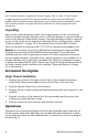
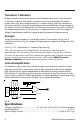
Bridge Switch
Many transducers configured as Wheatstone bridges with four resistive elements will
directly access the differential amplifier, as represented in Fig. 3. When the Bridge
switch is in the Differential position, both inputs of the differential amplifier, inverting
and non-inverting, are connected to the signal terminals of the transducer bridge. In
single-ended operation, the inverting input of the differential amplifier is connected
to a variable reference potential leaving the non-inverting input available to the
signal source. In the Gnd (ground) position both the inverting and the non-inverting
inputs are connected to ground.
+ out
- out
SHIELD
-
+
+5 v
-5 v
1
2
3
4
Fig. 3—This transducer is configured as a Wheatstone bridge with four resistive elements.