
Instruction manual

ISO-DAM8A
World Precision Instruments 13
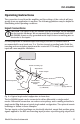
normal to set this control so that the recording device indicates zero when the
PROBE SELECT is in the GND position. The PROBE SELECT switch should be set
appropriately for the setup.
• If the headstage is used, set the switch to PROBE.
• If direct connection is made to the Iso-DAM8A input, set the switch to INT.
The GAIN control should be set so that the desired signal produces a significant
(>30% of full scale or so) on the recording device. If the recording device has a gain
or sensitivity control, it is usually preferable to set the recording device to a low gain
and the Iso-DAM8A to a high gain.
The HIGH and LOW filters should be used to reject noise outside the signal
frequency range. If the signal is transient in nature and DC response is not required,
the LOW filter should be set to the highest setting that does not distort the signal.
The HIGH filter should be set to the lowest setting that does not distort the signal.
If line noise is a problem, the NOTCH FILTER may be set to 50 or 60Hz, as
appropriate for the power system. Use of the notch filter can severely distort some
signals.
If a large DC offset is present in the setup, the DC OFFSET control can be used to
cancel it. The setting of this control can be quite sensitive, especially at high gain
settings.
Specifications
This unit conforms to the following specifications:
Voltage Gain ........................................................................................x10, x100, x1000, x10,000
Input Impedance to Gnd, each input ............................. > 10
12
Ω DC, 5 picofarads (typical)
Input R, Between Inputs .......................................................>10
12
Ω DC, 3 picofarads (typical)
Amp Noise, Input Shorted .......................................................................< 0.2µV rms (1-100Hz),
............................................................................................................................ < 1µV rms (1-10kHz)
Bandwidth .........................................................................................................................DC to 10kHz
High Filter (Low Pass) ...................................................................................... 0.1, 0.5, 1, 3, 10kHz
Low Filter (High Pass) ............................................................................................0.1, 1, 10, 300Hz
Input Offset Voltage Adjust. .................................................................................................± 1VDC
Common Mode Rejection ..................................... > 100dB @ 50/60Hz with <10Ω source
....................................................................................... 70dB typical with balanced 1MΩ source
Notch Filter Settings ................................................................................................50Hz, 60HZ, Off
Line Noise Rejection ................................................................................................................. >40dB
Output Voltage Swing ........................................................................................... ±10V Maximum
Output Resistance ......................................................................................................................... 200Ω
Output Position Adjustment .................................................................................................. ±1VDC
Power Source..........................................Power Adapter 110-120V/60Hz or 220-240/50Hz
Enclosure Dimensions ......................................................... 6.8 x 17 x 11.2˝ (17 x 43 x 28cm)
Shipping Weight ........................................................................................... 10–21 lb. (4.5–9.5kg)