
Instruction manual

12 World Precision Instruments
the Iso-DAM8A, whereas a positive-going signal applied to the BLACK inverting
input produces a negative-going output. The same holds true for the non-inverting
“+” input and inverting “–” input on the INPUT connector. Reversing the connections
from that shown simply results in an inverted signal.
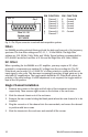
Output Connections
The output from each Iso-DAM8A module is available on the rear panel from a
standard BNC connector or all channels are available at the 25-pin connector. See
Fig. 3 for pin designations. The Iso-DAM8A output is suitable for application to any
recording or data acquisition device.
Grounding
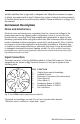
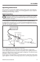
Proper grounding is critical to successful biological signal monitoring. The optimum
grounding configuration is the “single-point ground,” in which each component of a
monitoring setup is connected to a single point which is connected to earth or mains
ground. This grounding configuration is used in Fig. 3 and Fig. 4.
Shielding
The isolation feature of the Iso-DAM8A minimizes, but cannot eliminate, noise
pickup from electric distribution lines, fluorescent lights, computers, motors, radio
frequency transmitters, microwave ovens, etc. Use of shielded wires for input
connection is necessary if the subject is located more than a few inches from the
amplifier inputs. Even the use of shielded wires and proper grounding may be
insufficient in a high electrical noise environment, particularly if high impedance
electrodes are used, if the signal level is low (less than 100mV or so), or if high
frequency response is required. In these situations, the use of a metal shield, known
as a Faraday cage, which encloses the subject and the headstage may be necessary.
Idle Settings
If you are not certain what settings are required, the following settings are a good
starting point:
PROBE SELECT: GND
LOW FILTER: DC
DC OFFSET: OFF
GAIN: 10
HIGH FILTER: 10 kHZ
NOTCH FILTER: OFF
POSITION: Mid-range
POWER: OFF
Control Adjustment
After connecting inputs and outputs, the amplifier can be turned on. The POSITION
control may be used to establish a baseline setting on the recording device. It is