
Instruction manual


ISO-DAM8A
World Precision Instruments 11
Operating Instructions
The connection to and from the amplifier and the settings of the controls will vary
greatly from one application to another. The following guidelines may be helpful in
establishing initial operating conditions.
Input Connections
CAUTION: The inputs to the Iso-DAM8A and the headstage can be damaged
by electrostatic discharge. We recommend that you momentarily touch the
Iso-DAM8A chassis or any grounded metal object before connecting wire or
electrodes to the inputs.
It is very important to minimize input lead length, and use of shielded cable is
recommended for any leads over 2 or 3 inches (except grounding leads). Both the
inverting and non-inverting inputs must be connected. A “floating” (non-connected)
input will cause amplifier saturation.
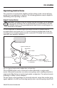
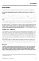
DAM50, DAM60, DAM70
Micromanipulator
#5489 Probe
#2033 Adapter
#5469 Metal
Microelectrode
Adapter
Metal Microelectrode
(i.e., TM33B01)
EP2
Ag/AgCl Half Cell
Prep
A
B
Central Ground
#3294 Grounding Clip
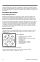
Fig. 4—A typical single-ended configuration is shown here.
The Iso-DAM8A inputs can be connected in either differential or single-ended
modes. Differential connection can reduce noise pickup, and is usually preferable to
single-ended. Fig. 4 shows a typical single-ended configuration. The optional remote
headstage is shown in these examples.
The two inputs on the headstage are electrically identical, except that positive-going
signals applied to the RED non-inverting input produce a positive-going output from