
Instruction manual

10 World Precision Instruments
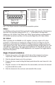
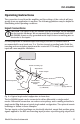
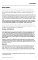
Pin 13
Pin 1
Pins 14 ~ 25
(bottom row)
NOT USED
Fig. 3—The 25-pin connector is used with data acquisition systems.
Filters
Iso-DAM8A provides selected filtering at both the high and low ends of its frequency
spectrum. The Low Filter settings are DC, 0.1, 1, 10 and 300Hz. The High Filter
settings are 100, 500Hz, 1kHz, 3kHz, and 10kHz. Typical settings recommended for
ECG and EEG would be Low Filter at 0.1Hz and the High Filter at 0.1kHz (100Hz).
DC Offset
When operating the Iso-DAM8A as a DC amplifier, you may require a DC offset
potential to compensate any existing DC voltage from the recording site. The DC
Offset knob can provide 0 to >100mV DC of either polarity to reduce (null) the net
input signal to zero volts. This becomes increasingly necessary if high gains are to be
used with DC amplification. The toggle switch below the DC Offset knob selects the
polarity of the offset voltage. If offset adjustment is not required, the toggle switch is
kept in the Off position.
Single Channel Installation
1. Remove two screws on the right and left sides of the instrument enclosure,
respectively. Then remove eight screws on the bottom of the enclosure.
2. Slide the internal chassis out of the enclosure.
3. Remove the two screws holding the blank panel where the new channel is to be
installed.
4. Plug the connector of this channel into the new module, and secure the channel
in position with two screws.
5. Slide the chassis into the enclosure and reinstall all the screws.
PIN FUNCTION PIN FUNCTION
1 Channel 1 8 Channel 8
2 Channel 2 9 Ground
3 Channel 3 10 Ground
4 Channel 4 11 Ground
5 Channel 5 12 Ground
6 Channel 6 13 Ground
7 Channel 7