
Instruction manual

ISO-DAM8A
World Precision Instruments 9
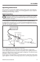
Input Cable
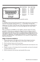
For convenience of connection to signal sources, each Iso-DAM8A module is
supplied with a 5-foot length of shielded input cable. One end is terminated in a DIN
plug which mates with the module. The other end has unterminated tinned leads.
The wires are color-coded as shown below:
Red + Input
Black – Input
White Isolated Ground””
Source Select Switch
The Source Select Switch sets the unit to operate either in the Internal Amplifier
(direct input mode) or the External Probe mode. When set to the Internal Amplifier
(INT), electrodes or other signal sources are connected directly to the INPUT
connector. When set to the PROBE position, the unit works with the optional
headstage. A center GND position disconnects all inputs to permit you to establish
a DC baseline with the POSITION control. Note that in this position, the DC OFFSET
and BAL (balance) adjustments have no effect.
Balance Adjustment
The DC balance potentiometer let you adjust the Gain switch position stability. This
potentiometer is accessible through a small screwdriver hole on the front panel.
To adjust the DC balance, connect the “+” and “-” inputs of the input connector, or
the headstage, if used, to Isolated Ground. Set the GAIN switch to 10. Using an
oscilloscope or recorder connected to the Output connector, adjust the POSITION
control so that the output trace on the recorder or oscilloscope is near the zero
volt level. Rotate the GAIN selector switch from x10 to x10000. If the baseline
moves, readjust the DC Balance potentiometer at the x10000 setting with a small
screwdriver until the baseline returns its prior setting. The baseline should not deflect
appreciably when the GAIN switch is reduced to lower values. The baseline should
remain essentially stable (with input grounded) as the Gain switch is rotated.
Output
The maximum signal output from any preamplifier channel is ±10V. All preamplifier
channels have individual coaxial (BNC) connectors on the rear panel of the
instrument. Channel numbers start with #1 on the left hand side (front view).
Channel outputs are also available on a 25-pin connector for use with data
acquisition systems.