
Instruction manual

SI-H Muscle Testers
4
WORLD PRECISION IN STRU MENTS
INSTRUMENT DESCRIPTION
Signal Conditioning Amplifi er for the SI-MT/SI-MKB/SI-
HTB
Front Panel
Power
Switch
Sarcomere
Spacing
Module
Anti
Oscillation
Unit
Optical
Transducer
Amplifier
Linear
Motor
Controller
Temperature
Control
Module
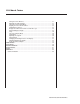
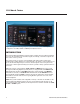
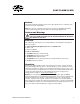
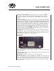
Fig. 4 The front panel of a Signal Conditioning Amplifi er System confi gured for a Muscle Tester
shows the SI-BAM21-LCB, the SI-AOSUB, The SI-SARCAM, the SI-MOTDB and the SI-TCMB2.
Optical Transducer Amplifi er–The SI-BAM21-LCB powers the force transducer and
converts the output of the transducer to an amplifi ed analog voltage that is proportional
to the force applied to the transducer. The output signal can be multiplied by a factor of 1,
2, 5 or 10 to provide better resolution for a minimal change in applied force.
Anti-Oscillation Unit (SI-AOSUB)–Each force transducer has a resonance frequency at
which it vibrates. The SI-AOSUB, when properly tuned to that resonance frequency,
removes the resonance noise from the output signal of SI-BAM21-LCB transducer
amplifi er. An SI-AOSUB is necessary when a linear motor is used.
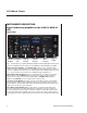
Sarcomere Spacing Module–Sarcomere spacing measurement requires a system with
an optical cuvette (cuvette with a window). A laser passes through the muscle, and the
diffracted light is captured with a CCD camera. By monitoring the diffraction pattern, the
length of the sarcomeres can be calculated.
Linear Motor Control Module–When a linear motor is required, this module powers
the motor and provides an output indicating the actual motor position. It connects to
an analog to digital converter output of the data acquisition system (like LabTrax 8/16)
to control the waveform and timing for the motor control. The output connects with an
analog input of the data acquisition system to monitor the sensor feedback from the motor.