
Instruction manual

SI-H Muscle Testers
34
WORLD PRECISION IN STRU MENTS
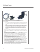
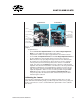
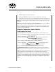
Fig. 33 (Left) The sarcomere grating fi ts into the cuvette and provides a foolproof calibration
method.
Fig. 34 (Right) The grating is position in the optical cuvette to calibrate the camera.
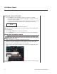
1. Turn on the system. See "Turning the System On" on page 24.
2. Enable the Laser. For safety reasons, the laser is always disabled on startup. See
"Turning On/Off the Laser" on page 30. When the laser is enabled, a red dot (the
laser beam) appears near the cross hair mark on the front of the camera.
3. Position a calibration grating inside the optical cuvette so that the laser beam shines
through the grating and casts a diffraction pattern on the camera lens (Fig. 34).
4. Adjust the zero order laser spot (the center beam) so that it hits the cross hair mark
on the camera. See "Aligning the Laser and the Camera" on page 32.
5. Using the Camera Height Adjustment Knob and the Laser Power Knob on the con-
troller to display the ideal signal for the fi rst order signal.
6. Read the sarcomere length on the LCD display.
7. Use the Camera X-Y Adjustment Knob to adjust the horizontal position control on
the camera until the sarcomere is displayed at 2.0µm.
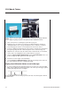
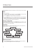
Display Laser Diffraction Pattern on an Oscilloscope
1. In order to display the laser diffraction pattern on an oscilloscope connect the Sync
BNC connector with the external trigger input of an oscilloscope. The trigger signal is
5.0V. It jumps high when the scan begins.
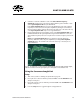
Fig. 35 The top trace shows the timing reference to the video. The camera signal is shown in
the bottom trace.