
Instruction manual

SI-MT/SI-MKB/SI-HTB
WORLD PRECISION IN STRU MENTS
33
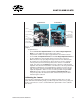
SI-SARCAM Front SI-SARCAM Back
Laser
AVOID EXPOSURE
Laser radiation emit
ted from this aperature
Avoid direct exposure to
the beam
Laser diode wavelength: 630–680nm
MaxOut: 5mW Class III
A Laser Product
Optical Cuvette
Cross Hair Mark
Camera
Laser X-Y
Adustment Knob
Laser Height
Adustment Knob
CCD Detector
Chip
Camera X-Y
Adustment Knob
Camera Height
Adustment Knob
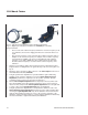
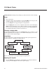
Fig. 32 The front and back of an SI-SARCAM system is shown mounted on an SI-MKB
platform.
To adjust the laser:
• Use the Camera X-Y Adjustment Knob and the Camera Height Adjustment
Knob for coarse alignment of the position of the camera.
• Verify that the camera's front plate is perpendicular to the main laser beam.
• Use the Laser X-Y Adjustment Knob and the Laser Height Adjustment Knob for
the fi ne alignment of the horizontal and the vertical position of the laser.
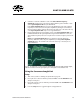
• When the camera is properly aligned the light of the fi rst order diffraction hits
the sensitive area of the CCD detector chip. It may be necessary to adjust the
vertical position (not the horizontal position) of the camera for a maximum
signal. To do this, press the Display button on the controller to view the signal
amplitude. This shows the detected fi rst order diffraction of the laser pattern. This
amplitude is maximal if the focused light hits the sensitive area of the detector
chip. To keep the signal from saturating the CCD and giving erroneous signals,
adjust the amplitude so that it is as close to 3.0V as possible. Using the Laser
Power knob on the controller and the Camera X-Y Adjustment Knob, you
can precisely position the CCD camera and control the laser power so that a
desirable signal is achieved.
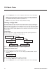
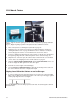
Calibrating the Camera
Your Sarcomere Length Unit comes with several calibration gratings. These are clear
plastic fi lms with an embedded grid (Fig. 33). When exposed to the laser, the grating acts
in place of the muscle to create a consistent diffraction pattern that is used to calibrate
the camera.