
Instruction manual

SI-MT/SI-MKB/SI-HTB
WORLD PRECISION IN STRU MENTS
29
6. Continue to rotate the calibration screw of the Anti-oscillation Frequency
Adjustment potentiometer to the right (clockwise) until the greatest number of bars
on the Signal Amplitude LED array are illuminated.
If the Signal Amplitude LED array becomes fully illuminated as the anti-oscillation
frequency is increased, decrease the pulse amplitude by turning its control knob to
the left (counterclockwise). Turn the knob to the left until some of the bars at the top
of the Signal Amplitude LED array are no longer illuminated.
7. Repeat Step 6 until the greatest number of bars on the Signal Amplitude LED array
is illuminated without the signal amplitude being saturated. When this occurs, the
anti-oscillation frequency has been set equal to the resonance frequency of the trans-
ducer.
NOTE: If the Signal Amplitude LED array is saturated at any time during the
frequency calibration, reduce the pulse amplitude by rotating Pulser Amplitude
Adjustment knob to the left until some of the bars at the top of the array are no
longer illuminated.
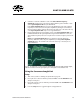
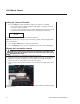
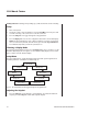
Fig. 24 The upper trace is a force transient obtained directly from the bridge amplifi er output,
and the lower trace shows the signal after it passes through the “anti oscillation” unit.
Using the Sarcomere Length Unit
Setup
1. Turn on the system. See "Turning the System On" on page 24.
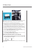
2. Line up the laser connector with the port labeled Laser on the SI-SARCAM module
and press it into place.
3. Line up the camera connector with the port labeled CCD on the SI-SARCAM module
and press it into place.
4. Press the Setup button to toggle through the setup parameters.