
Instruction manual

SI-H Muscle Testers
28
WORLD PRECISION IN STRU MENTS
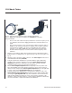
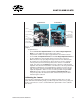
Fig. 22 (Left) This pulser assembly has no force transducer mounted in it.
Fig. 23 (Right) A force transducer is mounted in the SI-AOSUB pulser assembly.
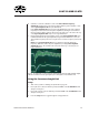
Keep in mind that:
• The closer the anti-oscillation frequency matches the resonance frequency of the
force transducer, the more the ringing phenomenon is removed from the force
signal.
• The resonance frequency can be evoked at anti-oscillation frequencies that are
multiples of the resonance frequency. For example, if the resonance frequency
of the transducer is 200Hz, it can also be evoked when the anti-oscillation
frequency is set to 400 or 600Hz. The anti-oscillation fi lter works best when
the anti-oscillation frequency is set at the actual resonance frequency of the
transducer.
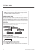
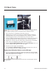
1. Slide the force transducer, with its tissue mount in position, forward into the pulser
( magnetic driver assembly) until it rests against the stop at the front of the pulser. See
Fig. 23.
2. Attach the cable of the pulser to BNC connector of the Pulser Output on the front of
the Anti-Oscillation module (SI-AOSUB).
3. Using the potentiometer adjustment tool provided with the signal conditioning
amplifi er system, rotate the calibration screw of the Anti-oscillation Frequency
Adjustment potentiometer completely to the left (counter-clockwise). The anti-
oscillation frequency is now set to the lowest possible level.
4. Turn the Pulser Amplitude Adjustment knob completely to the left (counter-clock-
wise). The amplitude of the anti-oscillation frequency is now set to the lowest pos-
sible level. Then, slowly turn the Pulse Amplitude Adjustment knob to the right until
a couple of bars on the Signal Amplitude LED array are illuminated.
5. Using the potentiometer adjustment tool, slowly turn the calibration screw of the
Anti-oscillation Frequency Adjustment potentiometer to the right (clockwise) while
observing the Signal Amplitude LED array. As the calibration screw is turned to the
right, the anti-oscillation frequency gets closer to the resonance frequency of the
transducer, and the transducer begins to oscillate at higher amplitude as indicated by
the increased number of lights in the LED array that illuminate.