
Instruction manual

SI-MT/SI-MKB/SI-HTB
WORLD PRECISION IN STRU MENTS
25
1. Setting a zero reference point with the force transducer un-loaded.
2. Applying a load with a known mass to the tissue mount on the transducer.
3. Choosing one of the two calibration methods to best serve the application. Use the
Gain Calibration Potentiometer to adjust the amplifi er’s output range to:
• Maximize the resolution for the intended measurement range. For the greatest
precision, maximize the resolution of the SI-BAM21-LCB by calibrating the 10.0V
output of the amplifi er to 10-20% above the maximum expected force. For
example, if the maximum expected value is 4.0-4.5g, set the SI-BAM21-LCB so
that a 5g mass yields a 10.0V output. The maximum expected output would then
be 9.0V, with a 4.5g applied load.
• Numerically correlate the force with a voltage output. For quick visualization, you
may choose to establish a numerical correlation by calibrating the SI-BAM21-
LCB so that a force like 5.0g generates a 5.0V output.
The following calibration procedure may be used with any SI-KG force transducer. For
illustration purposes, a SI-KG4 force transducer is used in the example. Note that a 5g
mass is the maximum force that a SI-KG4 can measure. If a gain of X10 is used with
theSI-KG4 transducer, then 0.5g, which is about 10% of the total range of the SI-KG4
force transducer, is the largest mass that can be used with this force sensor.
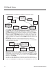
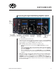
1. Connect the force transducer to the transducer input of the SI-BAM21-LCB. Connect
the output of the SI-BAM21-LCB, or the Corrected Output of the SI-AOSUB module
if it is being used, to an input of a data acquisition system or a digital multimeter. See
"Setup" on page 5.
• If a multimeter is used to track the output of the amplifi er or the anti-oscillation
fi lter, set the scale of the meter to measure DC voltages between -10.0 and
+10.0VDC.
• If a computerized data acquisition system, like a LabTrax 8/16, is used to record
the output of the amplifi er or fi lter, use the autoscale feature of the recording
software to track the changes in the output voltage as the calibration is
performed.
2. Mount the force transducer on the calibration stand on the base of the SI-MT, SI-
MKB or SI-HTB system.
NOTE: The calibration stand holds the force transducer and its tissue mount in the
proper orientation for an accurate calibration. This angle is critical in establishing
a proper calibration ratio. When gravity pulls the mass hung on end of the tissue
mount down, the actuator rod of the transducer is pulled in the same direction as the
force created by the tissue used in the experiment. If the force is not pulling on the
tissue mount in this direction, the output signal has to be adjusted correspondingly.