
Instruction manual

SI-H Muscle Testers
24
WORLD PRECISION IN STRU MENTS
OPERATING INSTRUCTIONS
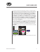
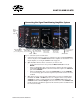
Turning the System On
For convenience, the Signal Conditioning Amplifi er System has two power switches, and
both must be on to power the system. One is located on the back panel, and one is on
the front. Both switches must be on to power the system. Verify that the power cord is
properly installed and plugged into an AC power outlet. All the modules power on/off
simultaneously. When the system is setup, just leave the back power switch in the on (I)
position.
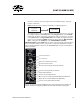
Using the SI-BAM21-LCB
Calibrating the SI-BAM21-LCB
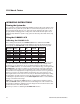
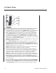
Before taking measurements, the SI-BAM21-LCB must be calibrated. Each SI-KG
force transducers shown responds linearly within its respective measurement ranges.
Consequently, the SI-BAM21-LCB can be calibrated using only two reference points.
Force
Transducer
Force
Range
Range
(g)
Noise
(µN)
Compliance
(nm/mN)
Resonance
Frequency
SI-KG2 0-2N 0-200 250 150 1.3kHz
SI-KG2A 0-0.5N 0-50 300
SI-KG4 0-50mN 0-5 15 0.5 1.2kHz
SI-KG4A 0-20mN 0-2 4 1 1.2kHz
SI-KG7 0-5mN 0-0.5 0.2 10 250Hz
SI-KG7A 0-5mN 0-0.5 0.4 5 500Hz
SI-KG7B 0-10mN 0-1.0 1 1.5 550Hz
SI-KG20 0-0.2N 0-20 80µN 590Hz
Under ideal conditions, use a model of SI-KG transducer that has a full-load range that
is no more than 120% of the maximum force that is anticipated. For example, if the
greatest force to be measured is 4g, use a transducer that has a full-load range of 5g,
like the SI-KG4 transducer. To use the transducer at its full-load range, set the gain of the
SI-BAM21LCB to X1. Higher resolutions are possible using the other gain settings (X2,
X5, or X10). However, using a gain of X10 allows only a tenth of the full-load range of
the transducer to be displayed as an output. In general, it is best to choose a gain factor
that does not need to be changed during an experiment, since each gain factor can
have slight variances in its offset. If it is necessary to switch between gain ranges during
an experiment, check the offsets in each of the ranges after the calibration and before
conducting the experiment. Then, use the Offset Adjustment switch to set the minimum
average offset between the ranges.
NOTE: Before calibrating the SI-KG transducer or setting its anti-oscillation frequency
with an SI-AOSUB module, position the tissue mount being used on the actuator rod of
the transducer. During the calibration, place the weight on the tissue mount at the same
position where the tissue will be attached.
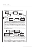
The basic procedure for calibrating the SI-BAM21-LCB involves: