
Instruction manual

SI-H Muscle Testers
22
WORLD PRECISION IN STRU MENTS
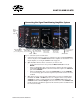
• IF the SI-BAM21-LCB transducer amplifi er module and the SI-AOSUB anti-
oscillation module are not connected to each other through the backplane of
the Signal Conditioning Amplifi er System, these two modules must be connected
through ports on the front panels of the modules. Use a BNC-BNC cable to
connect the Force Output port on the front panel of the SI-BAM21-LCB module
to the Input port on the front panel of the SI-AOSUB module.
• If a SI-AOSUB is being used because the system has a motor, then use a BNC
cable to connect the Corrected Output port of the SI-AOSUB module to the
analog input of the data acquisition system, which is designated as the force
recording channel. The Corrected Output is the signal from the transducer
amplifi er that exists after the resonance frequency of the transducer was
removed from the raw transducer signal by the anti-oscillation fi lter.
For information on using the SI-AOSUB, see "Using the Anti-Oscillation Unit" on page
27.
5. (Optional) If a Sarcomere Length Unit Is included, connect the SI-SARCAM as follows:
• Connect the cord from the laser to the Laser connection port.
• Connect the cord from the camera to the CCD connection port.
• (Optional) Connect the Video BNC port to an oscilloscope to display the laser
diffraction pattern.
• To monitor the approximate sarcomere length over time, connect the Sarcomere
BNC connector to an analog input on your data acquisition system.
• To track the distance from the center laser beam to the fi rst order of diffraction,
connect the Distance BNC connector to an analog input on your data acquisition
system.
For information on using the SI-SARCAM, see "Using the Sarcomere Length Unit" on
page 29.
6. (Optional) If cuvette temperature control is required, connect the SI-TCM2B as fol-
lows:
• Line up the cuvette connector on the heating cable of the cuvette with the CH1
or CH2 port on the SI-TCM2B, press it into place and screw the outer ring of the
connector to secure the connector. A second cuvette may be connected to the
other port, if necessary.
• To monitor the temperature over time, use a USB cable to connect a computer's
terminal emulation program using the USB port on the SI-TCM2B.
For information on using the SI-TCM2B, see "Using the Temperature Control Module"
on page 35.
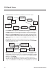
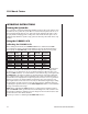
7. (Optional) If a Constant Load Module is installed, the connections that are made
depend upon the mode of operation. Three modes are available (Constant Load,
External Loop and Bypass). Make the connections according to the following table: