
Instruction manual

SI-MT/SI-MKB/SI-HTB
WORLD PRECISION IN STRU MENTS
21
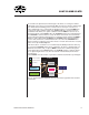
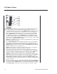
Connecting the Signal Conditioning Amplifi er System
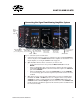
Fig. 20 Connect the system as shown above.
1. Connect the 5-pin connector on the force transducer to the port labeled Transducer
on the front panel of the SI-BAM21-LCB transducer amplifi er. For information on us-
ing the amplifi er, see "Using the SI-BAM21-LCB" on page 24.
2. (Optional) Make the linear motor connections, if a motor is used.
• Connect the linear motor to the port labeled Motor Connector on the SI-
MOTDB.
• Using a standard BNC cable, connect the analog output of the data acquisition
system (like LabTrax8/16) that controls the linear motor input to the Position In
port on the SI-MOTDB.
• Using a standard BNC cable, connect the Position Out port on the SI-MOTDB
to a second analog input of the data acquisition system that monitors the motor
feedback.
3. (Optional) If a motor is used, an anti-oscillation unit is necessary to minimize vibra-
tion. When the SI-MT or SI-MKB electronics are confi gured at the factory with an
SI-AOSUB, the signal is routed internally from the SI-BAM21-LCB module to the
SI-AOSUB module. The Force Output connection on the front of the SI-BAM21-LCB
module shows the raw unfi ltered signal from the transducer, but it does NOT need to
be connected externally.
Force
Transducer
5-pin
cable
Linear
Motor
Data Acquisition
Analog Input
(Force recording channel)
Data Acquisition
Analog Output
(Motor Position
Control channel)
Data Acquisition
Analog Input
(Motor Position
Control channel)
SI-H Cuvettes
Computer
(data logging through
terminal emulation
program)
Data Acquisition
Analog Input
(Sarcomere channel)
Data Acquisition
Analog Input
(Distance channel)
Laser Camera