
Instruction manual

SI-H Muscle Testers
20
WORLD PRECISION IN STRU MENTS
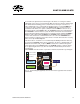
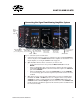
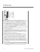
Stretch Control Knob–This 12-position dial adjusts the response time of the stretch and
slack periods of the tissue sample. The setting you choose depends on the sensitivity of
your force transducer and the strength of your sample tissue.
Force Step Dial–During a tonic contraction, activation of the SI-COLUB unit causes the
force to drop to the level, which is set using with the Force Step dial. The numbers on the
vernier dial correspond to the percentage of the force (F
o
) gained by the muscle up to the
point where the SI-COLUB module is triggered. The number 10.0 corresponds with 100%
of the force. For example, adjusting the potentiometer to 5.0 means that the applied force
drops to 50% of the original force F
o
. When the lever on the top right of the vernier dial is
in the lower position, the value of the dial is locked in place.
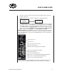
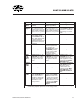
Restretch Velocity Potentiometer–Use a small screwdriver or POT tweeker to adjust the
speed at which the muscle returns to the original force.
Slack Poteniometer–Use a small screwdriver or POT tweeker to adjust the speed at which
the muscle is relaxed after the unit is triggered.
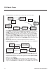
External Command Toggle Switch–When using the Constant Load mode, set this switch
to CL (down). When using the External Loop mode, set it to EXT CMD (up). It is not used
with Constant Load Bypass mode.
Constant Load Bypass BNC–This input determines whether or not the SI-COLUB is in
Bypass mode. When you want to use Bypass mode, connect this BNC terminal to an
output from LabTrax 8/16 and supply a continuous high voltage (greater than 3V) to it.
When using the other modes, this connection is not used. If desired, it could be tied to ground
or a 0.0V load could be placed on it.
Capture BNC–In the Constant Load mode, connect this port with the control signal from
the LabTrax 8/16. A digital output "High" signal allows the Force Step setting to slack. A
digital output "Low" signal sends the starting force stretch command.
Alternate Feedback BNC–This connection is only used for the External Command mode.
It connects the Constant Load Unit with the alternate feedback source, like the SI-
SARCAM camera. For example, a signal from the SI-SARCAM camera can be connected
to this input to be used as the parameter being driven to a desired commanded level.
Motor Position Command Output BNC–For all three modes, this port connects with the
Position In port on the SI-MOTDB Linear Motor controller. In the Bypass mode, the signal
that comes into the Bypass Motor Command input is transferred directly to the Motor
Position Command Output and sent to the SI-MOTDB Linear Motor Controller without
any modifi cations.
Bypass Motor Command BNC–This connection is only used in Bypass mode. It receives
input from the LabTrax 8/16. That signal goes directly to the Motor Position Command
Output and is sent to the SI-MOTDB Linear Motor Controller without any modifi cations.
Constant Load Command BNC–When in Constant Load mode, connect this BNC to the
Corrected Output on the SI-AOSUB. In External Loop mode, connect this input to an
output of the LabTrax 8/16 that is programmed to drive the motor and set the desired
level of force that is to be maintained during the experiment.