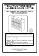
Kozy-World VENT-FREE GAS-FIRED ROOM HEATER USER'S OPERATION AND INSTALLATION MANUAL MODELS:KW(N305,P306)-30,000 BTU/HR AND KW(N205,P206)-20,000 BTU/HR WARNING:If the information in this manual is not followed exactly, a fire or explosion may result causing property damage, personal injury, or loss of life. - Do not store or use gasoline or other flammable vapors and liquids in the vicinity of this or any other appliance. - WHAT TO DO IF YOU SMELL GAS ● Do not try to light any appliance.
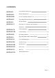
CONTENTS SECTION I- General Safety Instructions 2 SECTION II- Product Identification 3 SECTION III- Local Codes/National Fuel Code 3 SECTION IV- Unpacking the Heater Package 4 SECTION V- Product Features 4 SECTION VI- Fresh Air for Combustion and Ventilation 4 Installation 5 SECTION VII- Gas Requirements 9 SECTION VIII- Leak Checking 10 SECTION IX- Operating the Heater 11 SECTION X- Inspecting Burner & Pilot Burner Flames 14 SECTION XI- Care And Maintenance 15 SECTION XII-
GENERAL SAFETY INSTRUCTIONS: SAFETY : Accidents are always tragic especially because so many of them could have been prevented with a little care and judgment. There are some basic good practices we hope you will follow for safe use of your gas-fired room heater. IMPORTANT : Read this user's manual carefully and completely before trying to assemble, operate, or service this heater.
✑ If heater shuts off, do not relight until you provide fresh, outside air. If heater keeps shutting off, have it serviced. ✑ Do not run heater where : Flammable liquids or vapors are used or stored. Dusty condition exists. ✑ Never place any objects on the heater. ✑ Supervise children when they are in the same room with heater, never allow them to sit, stand or play on or around the heater. ✑ Make sure grille guard is in place before running heater. ✑ Do not use heater if any part has been under water.
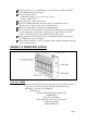
UNPACKING: 1. Remove heater from carton. 2. Remove all protective packaging applied to heater for shipment. 3. Check heater for any shipping damage. If heater is damaged, promptly inform dealer/distributor where you bought heater. PRODUCT FEATURES: Safety Device This heater has a pilot with an Oxygen Depletion Sensor Shutoff System (ODS). The ODS pilot is a required feature for vent-free room heaters. The ODS pilot shuts off the heater if the normal air oxygen content is reduced to 18%.
Unconfined Space An unconfined space whose volume is not less than 50 cubic feet per 1,000 BTU/HR of the aggregate input rating of all appliances installed in that space. Rooms communicating directly with the space in which the appliances are installed, though openings not furnished with doors are considered a part of the unconfined space. Confined Space A confined space whose volume is less than 50 cubic feet for each 1,000 BTU/HR of the aggregate input rating of all appliances in that space.
in high traffic areas in windy or drafty areas IMPORTANT : Vent-free heaters add moisture to the air. Although this is beneficial, installing heater in rooms without enough ventilation may cause mildew formation from too much moisture content. See National Fuel Code for Fresh Air for Combustion and Ventilation. This appliance may be installed in an aftermarket* manufacture (Mobile) home, where not prohibited by state or local codes.
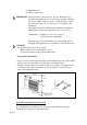
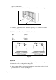
1. Install mounting brackets on wall as shown in Figure 2. Use enclosed “paper template” for proper location of holes. It may be necessary to use plastic or lead anchors for plaster walls. 2. Drill holes at marked locations using 9/64"drill bit. 3. Insert mounting screws through bracket and into wall studs. 4. Tighten screws until mounting bracket is firmly fastened to wall studs.
anchor or drilled hole. 8. Tighten both screws until heater is firmly secured to wall. Do not over tighten. Figure 5 1. Clearance requirements from surface of carpeting, tile or other combustible material (See Figure 1.). Wall Mounted & Floor Mounted With Base Provided Rear Sides Top Floor 0 Inches 6 Inches 36 Inches 2 Inches Figure 6 NOTICE: Maintain the minimum clearances shown in Figure 1, but you can provide greater clearances from floor, ceiling and adjoining wall. 2.
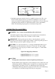
Figure 7 3. Installation and repair should be done by a qualified service person. The room heater should be inspected before use and at least annually by a professional service person. More frequent cleaning may be required due to excessive lint from carpeting and other materials. It is imperative that the control compartments, burners and circulating air passageways of the heater be kept clean. CONNECTING TO GAS SUPPLY : WARNING : Never connect an unregulated gas line to the heater.
Figure 8 LEAK CHECKING: GENERAL : Although all gas connections on the heater are leak tested at the factory prior to shipment, a complete gas tightness check must be performed at the installation site due to possible mishandling in shipment, or excessive pressure unknowingly being applied to the appliance. Periodically check the whole system for leaks, or immediately check if the smell of gas is detected. BEFORE TESTING Do not smoke while leak testing. Extinguish all open flames.
LEAK TESTING HEATER GAS CONNECTIONS: 1. Open manual shutoff valve. 2. Open main gas valve located near gas meter. 3. Make sure control knob of heater is in the OFF position. 4. Check all joints from manual gas valve up to gas control and including the manifold assembly. Apply the soap solution around the connections, valve and tubing. Soap bubbles will appear where a leak is present. 5. If a leak is present, immediately turn off gas supply, tighten any leaky fittings, turn gas on and recheck. 6.
Use only your hand to push in or turn the gas control knob. Never use tools. If the knob will not push in or turn by hand, don’t try to repair it, call qualified service technician or gas supplier. Force or attempted repair may result in a fire or explosion. Do not use this appliance if any part has been under water. Immediately call a qualified service technician to inspect the appliance and replace any part of the control system and any gas control component which has been under water.
Note : If pilot goes out, repeat steps 3 through 7. TO TURN OFF GAS TO HEATER Shutting Off Heater 1. Turn control knob clockwise to the OFF position. Shutting Off Burner Only(pilot stays lit) 1. Turn control knob clockwise to the PILOT position. CAUTION Do not try to adjust heating levels by using the manual shutoff valve.
Note : The thermostat sensing bulb measures the temperature of air near the heater cabinet. This may not always agree with room temperature (depending on housing construction, installation location, room size etc.). Frequent use of your heater will let you determine your own comfort levels. MANUAL LIGHTING INSTRUCTIONS 1. Remove lower front panel. 2. Follow steps 1 through 4 as stated under Lighting Instructions. 3. Press and turn control knob counterclockwise to the PILOT position. 4.
WARNING : If yellow tipping occurs, your heater could produce increased levels of carbon monoxide. If burner flame pattern shows yellow tipping, follow instructions at bottom of this page. NOTICE : Do not mistake orange flames with yellow tipping. Dirt or other particles etc. enter the heater and cause transient patches of orange flame. CARE AND MAINTENANCE : Dust, list or debris may affect heater performance. The heater draws air into it during normal operation.
TROUBLESHOOTING: PROBLEM Page 16 POSSIBLE CAUSE WHAT TO DO When control knob 1. Ignitor electrode posiis pressed in and tioned wrong. turned counterclockwise 2. Ignitor electrode broken. to ignition, there is no 3. Ignitor cable pinched or spark at ODS pilot. broken. 4. Ignitor cable not connected to ignitor electrode. 1. Replace Ignitor electrode. 2. Replace electrode. 3. Free ignitor cable, if damaged replace it. 4. Connect cable to electrode.
PROBLEM POSSIBLE CAUSE WHAT TO DO Burner backfiring during operation 1. Burner orifice is clogged. 2. Burner ports damaged. 1. Clean burner orifice. 2. Replace burner. Yellow flames during burner operation 1. Not enough air 1. Check air passageways and burner for dirt and debris(see care & maintenance.). Slight smoke and odor during initial operation 1. Residues from manufacturing processes. 1. Will stop after a few hours of operation. Heater produces a whistling noise when burner is lit. 1.
SPECIFICATIONS: MODELS INPUT RATING (BTU/HR,Variable) KW(N305,P306) N305 P306 KW(N205,P206) N205 P206 30,000/17,400 30,000/17,400 20,000/11,700 20,000/11,700 TYPE OF GAS NATURAL LP GASES NATURAL LP GASES REGULATOR PRESSURE SETTING 3.0″W.C. 8.0″W.C. 3.0″W.C. 8.0″W.C. 10.5″W.C. 4.0″W.C. 14.0″W.C. 11.0″W.C. 10.5″W.C. 4.0″W.C. 14.0″W.C. 11.0″W.C. INLET GAS SUPPLY PRESSURE: MAXIMUM MINIMUM SIZE OF HEATER (H×W×D) WEIGHT 23.8″×25.7″×8″ 23.8″×18.
PARTS LIST Page 19
PARTS LIST ITEM NO. DESCRIPTION 1. 2. 3. 4. 5. 6. 7. 8. 9. 10. 11. 12. 13. 14. 15. 16. 17. 18. 19. 20. 21. 22. 23. 23-1. 23-.2 24. 25. 26. 27.
LIMITED WARRANTY: This limited warranty is extended to the original retail purchaser of this Kozy-World Heater and warrants against any defect in materials in workmanship for a period of two (2) years from the date of retail sale. World Marketing of America, Inc., at it's option, will either provide replacement parts or replace or repair the unit, when properly returned to the retailer, within two (2) years of retail purchase.
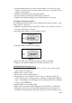
SOLVING COMMON PROBLEMS The 3 most common problems associated with any gas heater are gas leaks, wrong gas pressure and dirt. Do Not Use Your Heater Without Checking For Leaks! Leaks can occur during shipment and installation. A simple solution of soap and water dabbed on the fittings will bubble if a gas leak is present. Do not take short cuts! Wrong Gas Pressure! Too much gas pressure may severely damage your heater. Too little gas pressure and your heater will not burn correctly.