
Assembly Instructions for 3-Leg Front-Crank models User guide

Workrite Ergonomics | 800.959.9675 www.workriteergo.com 9
Workrite Sierra HX™ 3-Leg Crank Workcenters - Assembly Instructions
10
a
b
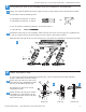
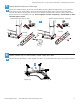
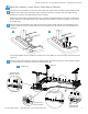
Base-OnlyModels:LooselySecureTableBasetoTabletop
Position the leg assembly on the face-down table top. Center the assembly on the table so that
neither of the side legs overlap the edge. Measure carefully to ensure that your table will be
positioned correctly as detailed below before drilling.
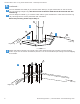
WiththeCrankHandlepushedallthewayin,positiontheMediumBraceasshowninthegure
below, based on your table depth. Then pull the Crank Handle out until its bracket is 3½" from
the table edge.
a
10½" for 30"
6¼" for 24"
3½"
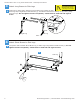
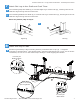
Drill the two leg assembly holes and the two holes for the Crank Handle corresponding to the
screws inside the circles. Insert these four Pan Head Screws (M) and be sure the handle turns
smoothly.
The Crank Handle can be installed on either side of the table. It is shown being connected to the
right leg.
b
Use the other screw holes to drill the remaining holes for each leg and the Crank Handle. Attach
the desk loosely at all points using Pan Head Screws (M).
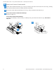
c
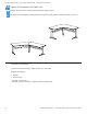
4 screws per
Crank Handle
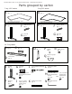
I
c
Left Leg
Right Leg
M
A
3 screws per
ShortBrace
C
6-10 screws
perLongBrace
B
4 screws per
MediumBrace
F