
Assembly Instructions for Front and Top-Crank models Instruction Manual

6 Workrite Ergonomics | 800.959.9675 www.workriteergo.com
Workrite Sierra™ Crank Workcenters - Assembly Instructions
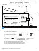
3-leg Tables, 120º corner:AssembleCenterLeg,thenlayoutthemajorpieces
Forassemblyoftwo-piecetops,pleaserefertoseparateinstructions.
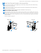
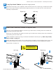
AttachTopBracketandCrossbarBrackettoCenterLeg.Use2ButtonHeadBoltstosecure
CrossbarBracketandfourtosecureTopBrackettoLeg.
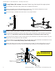
Placementofthelegsisveryimportant.Takethetimenowtolayoutthelegs,crossbarsandcrank
tubesintheproperlocation.NotethattheRightLegwillbeonyourleftandviceversawhenthe
assembly is upside down.
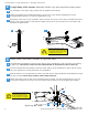
AttachCrankTubesandCrossbarstoLegsandTable
UseShortEndHexShafttoconnectCrankTubetogearmechanisminsideofCenterLegpointing
toRightLeg.The shorter end of the hex shaft should be inserted into the Center Leg.
UsesecondShortEndHexShafttoconnectCrankTubetogearmechanisminothersideofCenter
Leg. See diagram for correct placement and orientation.
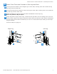
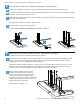
SlideCrossbarsoverLegBracketsonCenterLegandsecureusingtwoButtonheadMachineScrews
foreachCrossbar.Base-Only models, please skip to Step 4.
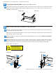
AttachtopplateofLegtodeskusing4WoodScrewsprovided.Usethelocatingholes.Ifyouuse
anelectricscrewdriver,besureitisonthelowesttorquesettingtoavoidstrippingthethreads.
c
a
d
I
B
H
C
A
D
b
a
b
c
b
3
To avoid stripping the threads when
attaching crossbars, always insert
and make the rst few turns of
the screw BY HAND with an Allen
wrench, ensuring it is in straight.
2
d
a
Legs must be positioned in correct
orientation for table to function. Note
that the Left Leg is labeled “Sierra Crank
V1” on the back near the top. The Right
Leg is labeled “Sierra Crank V2.”
RightLeg
Left Leg
Left Leg
RightLeg
L
J
P
I
M
c
b c
E
G
D
F
H