
Assembly Instructions for Front and Top-Crank models Instruction Manual

2 Workrite Ergonomics | 800.959.9675 www.workriteergo.com
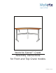
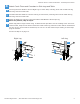
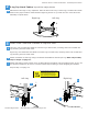
Workrite Sierra™ Crank Workcenters - Assembly Instructions
Each
Sierra
Crank
leg is
unique.
If not put together
in the correct order,
the table will not
function properly.
Legs are designated
as V1 or V2.
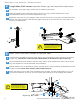
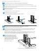
For assembly of two-piece tops, please
refer to separate instructions.
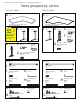
N
Crank Handle Assembly
Qty: 1
H
Crossbar
Qty: 2
J
¼-20x⅝”Buttonhead
MachineScrews
Qty: 8
A
Tabletop(sizeandshapedifferforeachmodel)
Qty: 1
B
Side Leg V1
Qty: 1
D
CenterLeg
Qty: 1
D
CenterLeg
Qty: 1
K
5
/
32
"AllenWrench
Qty: 2
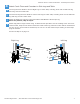
Parts grouped by carton
3-leg 120º tables
P
#12x¾"Phillips
headScrews
Qty: 20
M
Long End Hex
Shaft
Qty: 2
L
ShortEndHex
Shaft
Qty: 2
For assembly of two-piece tops, please
refer to separate instructions.
A
Tabletop(sizeandshapedifferforeachmodel)
Qty: 1
B
Side Leg
Qty: 2
3-leg 90º tables
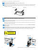
O
Crank Handle Connector
Qty: 1
I
Crank Tube
Qty: 2
C
Side Leg V2
Qty: 1
E
TopBracket
Qty: 1
F
Crossbar
Bracket
Qty: 1
G
¼-20x⅝”Buttonhead
MachineScrews
Qty: 6
E
TopBracket
Qty: 1
F
Crossbar
Bracket
Qty: 1
G
¼-20x⅝”Buttonhead
MachineScrews
Qty: 6
N
Crank Handle Assembly
Qty: 1
H
Crossbar
Qty: 2
J
¼-20x⅝”Buttonhead
MachineScrews
Qty: 8
K
5
/
32
"AllenWrench
Qty: 2
P
#12x¾"Phillips
headScrews
Qty: 20
M
Long End Hex
Shaft
Qty: 2
L
ShortEndHex
Shaft
Qty: 2
O
Crank Handle Connector
Qty: 1
I
Crank Tube
Qty: 2