
Assembly Instructions for Front and Top-Crank models Instruction Manual


10 Workrite Ergonomics | 800.959.9675 www.workriteergo.com
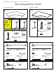
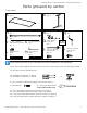
Workrite Sierra™ Crank Workcenters - Assembly Instructions
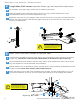
10⅞" from table
edge to mounting
hole for 30" base
versions
or
4
⅞" from table
edge to mounting
hole for 24" base
versions
4⅞" from
table edge to
mounting hole
6
a
b
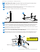
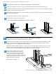
Base-OnlyFront-Crankmodels:SecureTableBasetoTabletop
ForBase-OnlyTop-Crankmodelspleaseskiptopage11.
Positionthelegassemblyontheface-downtabletop.Centertheassemblyonthetablesothat
neitherofthesidelegsoverlaptheedge.Measurecarefullytoensurethatyourtablewillbe
positioned correctly as detailed below before drilling.
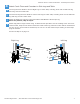
PositiontheCrankHandleConnectoroverthetwoholesnearesttheinsideoftheleg.Youmust
besurethatthecrankhandlewillclearthetabletopwhenextendedandthatthereisenough
clearanceinfrontofcrankhandleforcrankrotationandhandclearance.
DrillthetwolegholesfortheCrank
HandleConnectorandthetwoholes
intheCrankHandle.Insertthesefour
screwsandbesurethehandleturns
smoothly.Thenusetheotherscrewholes
todrilltheremainingholesforeachleg.
Attachthedeskatallpoints.
Skip to Step 7 on page 12.
a
b
5
a
b
c
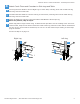
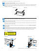
Front-Crankmodelsonly:AttachandConnectCrankHandle
AttachCrankHandleConnectortoLegbyinsertingtheshortendintotheholeintheleg.
IfyouhaveaWorkritetabletop,securetheCrankHandleConnectortothelegandtabletop,using
twoholesleftemptyinstep3,above.
AttachCrankHandleAssemblytoCrankHandleConnector,makingsurethatthehandleclearsthe
tabletopwhenextended.
Forbase-onlymodels,proceedtoStep6below.
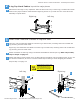
Secure to table using four wood screws.
IfyouhaveaWorkritetabletop,proceedtostep7.
d
a
10⅞" from table
edge to mounting
hole for 30" base
versions
or
4
⅞" from table
edge to mounting
hole for 24" base
versions
4⅞" from
table edge to
mounting hole
10⅞" from table
edge to mounting
hole for 30" base
versions
or
4
⅞" from table
edge to mounting
hole for 24" base
versions
4⅞" from
table edge to
mounting hole
N
O
P
P
b
c
d
10⅞"for30"
4⅞"for24"
4⅞"