Workrite Sierra™ Crank Assembly Instructions for Front and Top-Crank models #1500142 - Rev A
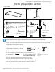
Workrite Sierra™ Crank Workcenters - Assembly Instructions Parts grouped by carton 3-leg 120º tables A 3-leg 90º tables Tabletop (size and shape differ for each model) Qty: 1 A For assembly of two-piece tops, please refer to separate instructions. For assembly of two-piece tops, please refer to separate instructions. Each Sierra Crank leg is unique.
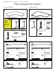
Workrite Sierra™ Crank Workcenters - Assembly Instructions Parts grouped by carton 2-leg tables A Tabletop (size and shape differ for each model) Qty: 1 B Leg Qty: 2 H Crossbar Qty: 1 N Crank Handle Assembly Qty: 1 I J Crank Tube Qty: 1 O Crank Handle Connector Qty: 1 P #12 x ¾" Phillipshead Screws Qty: 20 L 1 ¼-20 x ⅝” Button head Machine ScrewsQty: 4 Short End Hex Shaft Qty: 1 K M " Allen Wrench Qty: 1 5/32 Long End Hex Shaft Qty: 1 Q Crank Handle Qty: 1 OR P #12 x ¾" Phillipshea
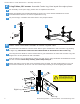
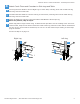
Workrite Sierra™ Crank Workcenters - Assembly Instructions 2 3-leg Tables, 90º corner: Assemble Center Leg, then layout the major pieces a b For assembly of two-piece tops, please refer to separate instructions. c Lay out the legs, crossbars and crank tubes in the proper location. Attach Top Bracket and Crossbar Bracket to Center Leg. Use 2 Button Head Bolts to secure Crossbar Bracket and four to secure Top Bracket to Leg.
Workrite Sierra™ Crank Workcenters - Assembly Instructions 4 Attach Crank Tubes and Crossbars to Side Legs and Table a Use Long End Hex Shaft to connect Right Leg to Crank Tube, inserting short end of shaft into leg and long end into Crank Tube. b Use Short End Hex Shaft to connect Left Leg to Crank Tube, inserting short end of shaft into leg and long end into Crank Tube. c Attach Crossbars to side legs using two Button head Machine Screws per leg. Base-only models, skip to step 5.
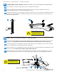
Workrite Sierra™ Crank Workcenters - Assembly Instructions 2 3-leg Tables, 120º corner: Assemble Center Leg, then layout the major pieces a b For assembly of two-piece tops, please refer to separate instructions. c Placement of the legs is very important. Take the time now to lay out the legs, crossbars and crank tubes in the proper location. Note that the Right Leg will be on your left and vice versa when the assembly is upside down. Attach Top Bracket and Crossbar Bracket to Center Leg.
Workrite Sierra™ Crank Workcenters - Assembly Instructions 4 Attach Crank Tubes and Crossbars to Side Legs and Table a Use Long End Hex Shaft to connect Right Leg to Crank Tube, inserting short end of shaft into leg and long end into Crank Tube. b Use second Long End Hex Shaft to connect Left Leg to Crank Tube, inserting short end of shaft into leg and long end into Crank Tube. c Attach Crossbars to side legs using two Button head Machine Screws per leg. Base-only models, skip to step 5.
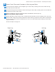
Workrite Sierra™ Crank Workcenters - Assembly Instructions 2 a 2-leg Front-Crank Tables: Layout the major pieces Placement of the legs is very important. Take the time now to lay out the legs, crossbars and crank tubes in the proper location. Note that the Right Leg will be on your left and vice versa when the assembly is upside down.
Workrite Sierra™ Crank Workcenters - Assembly Instructions 2 a 2-leg Top-Crank Tables: Layout the major pieces Placement of the legs is very important. Take the time now to lay out the legs, crossbars and crank tubes in the proper location. Note that the Right Leg will be on your left and vice versa when the assembly is upside down.
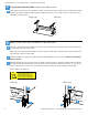
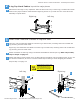
Workrite Sierra™ Crank Workcenters - Assembly Instructions 5 Front-Crank models only: Attach and Connect Crank Handle a b Attach Crank Handle Connector to Leg by inserting the short end into the hole in the leg. c Attach Crank Handle Assembly to Crank Handle Connector, making sure that the handle clears the or table top when extended.
Workrite Sierra™ Crank Workcenters - Assembly Instructions 6 a Base-Only Top-Crank models: Secure Table Base to Tabletop For Base-Only Front-Crank models please see page 10. Position the leg assembly on the face-down table top. Center the assembly on the table so that neither of the side legs overlap the edge. Measure carefully to ensure that your table will be positioned correctly as detailed below before drilling.
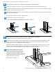
Workrite Sierra™ Crank Workcenters - Assembly Instructions 7 Tighten All Screws and Flip Table Over a b c 8 Tighten all Wood Screws connecting handle and legs to desk. Flip table over and adjust Leveling Glides if required so that table is steady and does not rock. Top-Crank models only: Insert Crank Handle into hole in worksurface over the right leg so that it engages the gearbox. Turn Handle to raise or lower table.
Workrite Sierra™ Crank Workcenters - Assembly Instructions Replacement Part Numbers Crank (Used Crank (Used Crank (Used Handle Assembly, 9¾/12................................ Part# 6100085-09.73-12.00 on 24” deep tables) Handle Assembly, 11½/12............................... Part# 6100085-11.50-12.00 on 30" deep tables) Handle Assembly, 11½/16............................... Part# 6100085-11.50-16.00 on 2-Leg Front Crank Curved-Front Table) Sierra Front Crank Handle, 11½"L.............................
Workrite Sierra™ Crank Workcenters - Assembly Instructions 14 Workrite Ergonomics | 800.959.9675 www.workriteergo.