28i RSF WALL MOUNTED COMBINATION BOILER FOR CENTRAL HEATING AND MAINS FED DOMESTIC HOT WATER INSTALLATION AND SERVICING INSTRUCTIONS This appliance is for use with Natural Gas Cat I2H GC NUMBER N.G. 47 311 54 BOILER OUTPUT To Domestic Hot Water – Modulated Control Minimum 8.5 kW Maximum 27.5 kW To Central Heating – Modulated Control Minimum 10.5 kW Maximum 27.5 kW THESE INSTRUCTIONS APPLY IN THE UK ONLY AND MUST BE LEFT WITH THE USER OR AT THE GAS METER.
Contents 1. Installation Regulations . . . . . . . . . . . . . . . . . . . . . . . . . . . Page 2. Introduction . . . . . . . . . . . . . . . . . . . . . . . . . . . . . . . . . . . . . Page 3. Technical Data . . . . . . . . . . . . . . . . . . . . . . . . . . . . . . . . . . . Page 4. Siting the Appliance . . . . . . . . . . . . . . . . . . . . . . . . . . . . . . Page 5. Siting the Flue. . . . . . . . . . . . . . . . . . . . . . . . . . . . . . . . . . . . Page 6. Air Supply . . . . . . . . . . . . . . .
An optional vertical flue kit to provide for flue lengths up to 3400mm including vertical flue terminal. A terminal guard, Type K2, GC 393 553, is available from Tower Flue Components, Vale Rise, Tonbridge, TN9 1TB. Do not allow the flue terminal fitted to the outside wall to become obstructed or damaged. A kit for internal fixing of the flue is available separately. 2.6 Controls Central Heating Temperature control knob. A facia mounted programmer is provided.
The data plate is fixed to the inner casing cover. 3. Technical Data Table 1. NOMINAL BOILER RATINGS (10 Minutes After Lighting) BOILER ADJUSTED FOR G20 (Natural Gas) BURNER OUTPUT INPUT (Net) GAS RATE PRESSURE kW kW m bar. m3/h 8.5 10.5 1.0 1.11 10.5 13.5 1.5 1.38 27.5 30.0 13.5 3.17 * ** Natural Gas: Net Input = Gross Input x 0.901 * Hot water setting - manual adjustment **Central heating setting - non adjustable Table 2.
Table 5 PERFORMANCE SPECIFICATIONS litres 3.0 MAXIMUM MAINS INLET PRESSURE PRIMARY WATER CAPACITY bar 10 MINIMUM MAINS INLET PRESSURE (WORKING) FOR MAXIMUM FLOW bar 0.9 MINIMUM MAINS INLET PRESSURE (WORKING) FOR OPERATION bar 0.1 MAXIMUM CENTRAL HEATING FLOW TEMPERATURE °C MAXIMUM CENTRAL HEATING SYSTEM PRESSURE (OPERATING) bar 82 (nom) 2.5 MINIMUM CENTRAL HEATING SYSTEM PRESSURE bar 0.5 OUTPUT TO DOMESTIC HOT WATER kw NATURAL GAS (G20) 8.5 - 27.
Fig. 3. Appliance casing dimensions and required clearances (front view). 4. Siting The Appliance 4.1 The appliance may be installed in any room but refer to the requirements of the current IEE Wiring Regulations BS 7671 and, in Scotland, the electrical provisions of the Building Regulations applicable in Scotland, with respect to the installation of appliances in rooms containing baths or showers.
5. Siting The Flue 6. Air Supply 5.1 The flue must be installed as specified in BS 5440:Part 1. 5.2 The terminal must not cause an obstruction nor the discharge cause a nuisance. Refer to Fig. 7. 5.3 If a terminal is fitted less than 2 metres above a surface to which people have access then a guard must be fitted. The guard must be evenly spaced around the terminal and fixed with plated screws. A type K2 guard is available from Tower Flue Components, Vale Rise, Tonbridge, TN19 1TB. 5.
7.7 Water loss must be replaced. See Fig 4. The connection should be made in the central heating return as close to the appliance as possible. A filling loop kit is supplied. 7.8 Repeated venting loses water from the system. It is essential that this water is replaced and the system pressure maintained. 7.9 Connections to the mains water supply must not be made without the authority of the local Water Company. 7.10 The pump is set at maximum and should not be adjusted. 7.
. Domestic Hot Water 10. Gas Supply 9.1 The following are general requirements and, if necessary, reference should be made to the local Water Company before fitting the appliance. 9.2 MAINS COLD WATER INLET. Devices capable of preventing the flow of expansion water must not be fitted unless separate arrangements have been made. A mini expansion vessel kit is available which contains the necessary parts for fitting an internal expansion vessel to the appliance. Refer to Section 19.
11.7 If a room thermostat and/or external programmer is to be fitted refer to Figs 12 and 13. The devices must be suitable for use with mains voltage. 11.8 A facia mounted mechanical programmer is available as an optional extra. Instructions are supplied with the programmer kit. 11.9 A time switch or programmer can be fitted externally to the appliance. 11.10 The boiler provides automatic frost protection, the use of a frost thermostat is not recommended.
CH control POT X6 X6 Pins 5,6 & 7 X6 X6 Pins 8 & 9 X6 Modulating valve Pins 15 & 16 X6 Overheat stat Air pressure switch Pins 14,17 & 18 Flow signal Pins 19 & 20 CH temp. sensor Pins 3 & 4 DHW temp. sensor Fig. 10. Functional flow diagram.
Fig. 11. Mains electricity connections. 230V N L X2 ue Bl Brown X1 Blue Gre en/ yel low Brown Strain relief clamp Green/yellow Programmer and room thermostat Fig. 13. 230V programmer connections. Fig. 12. 230V room thermostat connections.
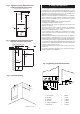
Mark the centre-lines of the pipe connections to aid the preplumbing of the system pipework. Check the position of the fixing points and the flue opening before drilling the fixing holes 60mm deep for the No.12 size plugs and cutting the flue duct hole at 110mm diameter (150mm diameter for internally fitted flues. 12.5 Wall Mounting Plate and Manifold Fit the plugs and fix the top support to the wall. Refer to Fig. 14. Check the top support is properly aligned before tightening the screws. 12.
The standard telescopic flue assembly is suitable for flues from 425mm (without cutting) up to 725mm measured from the centre-line of the boiler flue outlet to the outer face of the wall. Refer to Fig. 18. Fig.16. Appliance casing and control equipment fixings. Inner casing cover screws (4) If L is greater than 725mm then flue extension kits will be required - each kit extends the flue by 750mm up to a maximum of 2-5m. See table below.
Fig. 19. Extension Duct. L Turret assembly Terminal assembly Fixing screws Fixing screw Ducts of equal length Appliance casing Shorten first extension fitted to the turret assembly if more than one extension is fitted Fig. 21 . Rear flue. Fig. 20. Flue duct length (side flue).
Fig. 22. Flue Turret Fixing . Fig. 23. Terminal assembly for internal fitting of the flue. 1 5 1 2 3 4 1. 2. 3. 4. 4 3 2 Flue turret Clamp Appliance Fixing Screw 1. Flue centering ring 2. Air duct 3. Flue duct 4. Rubber sealing gasket 5. Flue Terminal Rubber sealing gasket Flue terminal 12.12 Flue Bends 90° and 45° bends are available. A maximum of two bends may be used in addition to the first bend on the flue turret. A 90° bend is equivalent to 750mm of straight duct.
Fig. 25 - Elbow to Flue Turret Assembly. Fig. 27 - Facia Connections Cover. 120mm 1 2 100mm Flue Turret Bend 3 Fig. 26 Vertical Adapter. 5 1. Control Panel Fixing Screws 2. Facia 3. Control Panel Pivot Point 4. Connection Cover 5. Connection Cover Fixing Screws Flue Duct Air Duct 12.14 Completion of the Installation Check that all the connections on the appliance have been tightened. Remove the facia bottom panel. Refer to Fig. 27.
Fig. 29 - Programmer Connection - Facia Position 4 3 1. Programmer 2. Programmer Fixing Clip 3. Pressure Gauge 4. Programmer Connector 2 1 Fig. 30. Appliance components and fixings (upper assembly). 13. Commissioning Reset Button Benchmark Water Treatment: For optimum performance after installation, this boiler and its associated central heating system should be flushed in accordance with the guidelines given in BS7593:1992 - Treatment of water in domestic hot water systems.
Fig. 33. Gas valve. Note: 1 bar = 10.2m = 33.5ft of water. 13.3 Set the System Pressure Fill the system until the pressure gauge is at 2.5 bar and check for leaks. Release water from the system using the relief valve test knob until the required system pressure is obtained, upto a maximum of 1.5 bar. Set the pointer on the pressure gauge to record the set system pressure. If the pressure indicated on the gauge is greater than 2.
13.8 Balance the system to give a temperature differential of 11°C or 13°C. A non-adjustable by-pass is fitted to the appliance. Refer to Table 3. 13.10 Set the room thermostat to minimum and check that the burner goes out. Reset the room thermostat to maximum and the burner will relight and follow the normal operating procedure. Turn off the gas service cock. The burner will go out but sparking from the electrode will continue for 10 seconds when the appliance will 'Lock-out'.
15. Inspection And Service Fig.35. Appliance casing and control equipment fixings. 15.1 SERVICING To ensure continued efficient operation of the appliance it must be checked and serviced as necessary at regular intervals. The frequency of servicing will depend upon the particular installation conditions and usage, but once per year should generally be adequate.
16. Replacement Of Parts Fig. 37. Burner and electrode assembly. Flame sense electrode 16.1 IMPORTANT Switch off the electricity and gas supplies before replacing any components. After the replacement of any components, check for gas soundness where relevant and carry out functional checks as described in Section 13 - Commissioning 16.2 COMPONENT ACCESS To replace components it is necessary to remove one or more sections of the cabinet and cover plates within the appliance as described in Section 15.3.
Fig. 38. Combustion chamber. Auto air vent Overheat Thermostat Heat exchanger Hot water connections Central heating connections Cut-outs in combustion chamber sides Pump bulk-head connector Flame Sense Electrode Spark Electrode Assembly Burner 10. Flame Sensor. See Fig. 39. Remove the burner as described in section 15.3(h). Undo the M3 screw and remove the sense electrode from the burner. Fit the replacement electrode in the reverse order, checking that the sense gap is 5 to 6mm. 11. Gas Valve.
To set the burner pressure. See Fig. 40. The minimum and maximum burner pressures must be set after a new gas control has been fitted. The maximum burner pressure must be set first, as any adjustment of the maximum pressure influences the minimum pressure setting. Start the appliance in the domestic hot water mode as described in section 13.6. - Appliance Operation. Adjust the maximum pressure adjustment (2mm Allen screw on the gas valve) to give a burner pressure of 13.5 mbar on natural gas.
Remove the four corner screws on the rear of the facia and separate the metal back panel from the plastic facia. Remove the flame sense and ignitor leads from the control board. Remove and retain the brass nut and washer. Release the six pillars on the control board and pull the control board forward off the back panel. Fit the replacement board in the reverse order ensuring it is pushed firmly onto the six pillars and clicks into place.
22. Flue flow sensor. See Fig. 46. Check that the electricity supply to the appliance is turned off. Remove the fan assembly as described in Section 15.3(e). Unscrew the single central retaining screw and withdraw the sensor from the fan. Fit the new sensor ensuring the correct orientation and carefully tighten the retaining screw. Refit the fan assembly in reverse order. Fig. 46. Flue flow sensor.
Pump on Water flow temperature monitored by central heating sensor Escape pause by resetting the mains electricity supply OFF-ON Is fan in overrun mode? YES NO Wait (pump on in central heating mode) FAIL Air pressure switch test PASS AUTOMATIC START-UP SEQUENCE Internal "Autofrostat" demand CENTRAL HEATING DEMAND Operating Switch (or programmer) and room thermostat on End of a domestic hot water overrun 1.
Inhibit operations for approximately 1 second. 6 second delay before reignition from any other demand. Run pump Burner pressure at 1.5 mbar 4°C to 8°C Above 8°C Burner never to be extinguished irrespective of the rate of temperature rise Monitor central heating sensor Below 4°C Commence normal central heating mode until heating temperature reaches 20°C Domestic hot water temperature monitored by hot water sensor Burner pressure adjusted based on the temperature rise over the previous minute.
18. Fault Finding CH control POT DHW temp. sensor Flow signal CH temp. sensor X6 Pins 3 & 4 X6 Pins 19 & 20 Air pressure switch X6 Pins 14, 17 & 18 X6 Pins 15 & 16 X6 Pins 5,6 & 7 Modulating valve X6 Pins 8 & 9 Overheat stat Note: This fault-finding information is for guidance only. Worcester Heat Systems cannot be held responsible for costs incurred by persons not deemed to be competent.
Fault in Domestic Hot Water Fault in Central Heating Is mains LED flashing? YES GO TO CHECK D YES NO NO Is mains LED illuminated? NO GO TO CHECK C NO Is mains LED iluminated? YES YES Is control knob set for demand? Is mains LED flashing? NO Turn control knob fully clockwise NO Ensure link is fitted at X2 pins 5 & 6 NO Set room stat to call for heat NO Ensure link is fitted at X2 pins 2 & 3 YES Is a room thermostat fitted? YES Is room thermostat calling for heating? YES Is programmer
No mains LED Is mains present at X1 pins 1 & 3? NO Connect mains supply YES Is Fuse F1 OK? NO Replace fuse YES Is F2 (1.
Overheat Thermostat Check The overheat thermostat can be reset by pressing the reset button, but if it trips immediately or on a regular basis a serious problem has occurred therefore contact your installer Reset thermostat Does button hold in? NO Is capillary broken? YES YES Is capillary firmly ATTACHED to exchanger? NO Replace overheat thermostat ATTACH to heat exchanger YES GO TO CHECK I Pump Check Is pump connector secure on the PCB (X3)? NO Secure Connector YES Is mains present at the pump
Thermistor Check Remove connectors from thermistor YES Is resistance between terminals of thermistor between 690ohms & 33k? NO Faulty thermistor YES Thermistor OK Harness Continuity Check Remove appropriate connectors YES Is continuity observed between each end of wire in question? NO Faulty harness or connector YES Harness OK Harness Short Check Remove appropriate connectors YES Is short circuit observed between pair of wires in question? NO Faulty harness YES Harness OK 33
Ignition Check Is fan running? NO GO TO CHECK G NO GO TO CHECK E NO Is sparking present at the electrodes? YES Does sparking occur? GO TO CHECK L Faulty PCB Replace YES Does ignition occur? NO YES YES Are ignition leads connected both ends securely? Are leads breaking down? YES Replace leads NO YES Is flame sense electrode in flame? NO Ensure flame sense electrode in flame at minimum burner pressure YES Is lead secure both ends? NO YES GO TO CHECK I HARNESS OK Faulty PCB Replace Do
L Air Pressure Switch Check Remove BROWN and WHITE terminals from air pressure switch With no demand, is a short-circuit observed at exposed APS terminals? NO Air pressure switch faulty YES Reconnect the WHITE & BROWN wire and remove the GREEN wire. Initiate a demand. Does the fan run? NO NO YES Fan or fan cable faulty YES With fan running disconnect BROWN wire. (DO NOT touch chassis with it).
N Modulating Valve Check Is minimum pressure observed at burner at all times? YES Remove X6, measure resistance between pins 15 & 16 NO NO GO TO CHECK I Is resistance nominally 125ohms? YES Is pressure at burner always the same? NO YES With pressure above minimum, remove Modureg Lead. Does pressure drop to minimum? NO Faulty modulating valve . Replace gas valve Reconnect X6 and measure voltage across modulating valve during operation YES Gas valve OK YES Does voltage go above 6.
19. Component Parts List Key No. 1 2 3 4 5 6 7 8 9 10 11 12 13 14 15 16 18 19 20 21 22 23 24 G.C. No. E01-892 375-697 E01-612 E01-930 E01-598 E01-599 E01-600 E01-601 299-506 375-699 E01-602 E01-603 E58-079 E04-582 E01-900 299-495 E01-605 324-822 E01-607 299 357 E01-610 ACCESSORIES 299-360 E05-341 Part Manufacturer’s Reference WHS Part No.
9 8 14 3 21 3 1 15 22 4 13 7 11 5 12 10 23 24 25 23 24 2 38 20 20 6 19 18 16
This manual is to be used in conjunction with the variant part number of the bar code below: Worcester Heat Systems Limited (Bosch Group), Cotswold Way, Warndon, Worcester WR4 9SW. Telephone: (01905) 754624. Fax: (01905) 754619. Technical Helpline (08705) 266241. www.worcester-bosch.co.uk This booklet is accurate at the date of printing but will be superseded and should be disregarded if specifications and/or appearances are changed in the interests of continued improvement.
Bosch Group SINGLE-CHANNEL MECHANICAL TIMESWITCH FITTING & OPERATING INSTRUCTIONS General information is given in the users instruction leaflet dispatched with the appliance and/or on the lighting instruction plate fitted on the appliance. THESE INSTRUCTIONS APPLY IN THE U.K.
Gas Safety (Installation and Use) Regulations 1984 : All gas appliances must be installed by a competent person, in accordance with the above regulations. Failure to install the appliance correctly could lead to prosecution. The manufacturers notes must not be taken, in any way, as overriding statutory obligations. IMPORTANT: Read these instructions carefully in order to get the best from your appliance.
i WIRING DIAGRAM TO REPLACE TIMESWITCH – CDi TO SET THE TIMESWITCH The timeswitch controls the operation of the central heating circuit. The domestic hot water is permanently available upon demand and will take priority over the supply of heat to the system during the demand.
TO SET THE CLOCK Turn the dial clockwise until the correct time of day is at the pointer. TO SET THE SWITCH To set the ON periods push the grey tappets towards the centre from the start of the period until the end of each period. OPERATIONAL NOTES Switching: The switching options for the central heating are OFF Off all the time AUTO On and Off as selected by the adjustment of the tappets ON On all the time. Hot Water Supply: Hot water is available whenever a tap or shower is turned on.
24i, 28i RSF COMBI G.C. NUMBERS NATURAL GAS L.P.G.
EXCELLENCE COMES AS STANDARD Thank you for purchasing a Worcester gas-fired combination appliance. Worcester appliances are made by Worcester Heat Systems and the strictest quality control standards are demanded throughout every stage of production. Indeed, Worcester Heat Systems have led the field in innovative appliance design and performance for more than 30 years.
GENERAL INFORMATION GAS SAFETY (INSTALLATION AND USE) REGULATIONS 1998 It is the law that all gas appliances must be installed by a competent person in accordance with the above regulations. Failure to install appliances correctly could lead to prosecution. It is in your interest and that of safety to ensure compliance with the law. The manufacturers notes must not be taken, in any way, as over-riding statutory obligations. WARNING: This appliance must be earthed and protected by a 3 amp fuse.
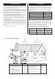
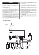
A flow restrictor is fitted within the appliance which limits the hot water delivery rate to a maximum of 8.0 (±15%) litres/minute (1.8 gallons/minute) 24i or 10 (±15%) litres/minute (2.2 gallons/minute) 28i. Hot Water and Central Heating mode: Fig. 1. System Diagram. Gas to water heat exchanger When a demand is made for heating by the system controls (i.e. a programmer or room thermostat). The pump will energise circulating primary water around the heating system and the burner will light.
GENERAL NOTES CENTRAL HEATING SYSTEM During the first few hours of operation of the central heating system, check that all radiators are being heated at an even rate. Should the upper area of a radiator be at a lower temperature than the base of the radiator, it should be vented by releasing air through the venting screw at the top of each radiator. Make sure your installer shows you how to carry out the operation.
SHOWERS, BIDETS, TAPS AND MIXING VALVES Standard hot and cold taps and mixing valves used with the appliance must be suitable for operating at the available mains pressure. Thermostatically controlled or pressure equalising shower valves will guard against the flow of water at too high a temperature. Hot and cold mains fed water can be supplied direct to an overrim flushing bidet subject to local water company requirements.
VENTILATION OF THE APPLIANCE This is a room sealed appliancem, any ventilation openings in a wall or door must not be obstructed. Do not allow the flue terminal fitted on the outside wall to become obstructed or damaged. If the appliance is fitted in a compartment do not use the compartment for storage purposes unless it conforms to the requirements of BS 6798:1987: Section 6 and the requirements of Section 6. Air Supply in the Installation Instructions.
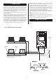
OPERATION OF CONTROLS (See also label on inside of appliance front panel). The appliance is fitted with the following controls: CENTRAL HEATING TEMPERATURE The position of this knob will determine the temperature of the water delivered to the radiators between the ‘I’ and ‘MAX’ position. When the knob is turned anti-clockwise past the ‘I’ position towards the ‘ ’ (Summer Position), then the appliance will operate in the HOT WATER mode only and no heat will be delivered to the radiators.
Fig. 2. 24i/28i Controls.
TO LIGHT AND STOP THE APPLIANCE TO LIGHT THE APPLIANCE Check that the water valves to the central heating circuit are open. Check that the grey needle on the pressure gauge is not below the required pressure. Switch on the mains electricity. The power on indicator will light. Set the room thermostat, if fitted, to maximum. Turn the central heating temperature control knob to ‘MAX’. The burner will light. Set the central heating control knob and the room thermostat, if fitted, to the desired temperature.
TO STOP THE APPLIANCE For Short Periods Turn the central heating temperature control knob fully anticlockwise to the ‘ ’ position. Domestic Hot Water will still be available as required. For Long Periods Switch off the mains electricity. A facia mounted mechanical programmer will require resetting once the mains supply has been disconnected. ELECTRICITY SUPPLY FAILURE If the electricity supply fails the appliance will not operate. Once the supply is restored the appliance will return to normal operation.
APPLIANCE FAILS TO OPERATE More than 30% of all calls made to Worcester Heat Systems to report appliance faults or breakdowns prove to be false alarms, as there is often a simple explanation for the apparent malfunction. So, to help you save time and money – not to mention frustration and inconvenience – please refer to the General Information, Notes and Lighting Instructions ensuring all controls are set correctly.
MAINTAINING YOUR APPLIANCE Your new Worcester gas-fired appliance represents a longterm investment in a reliable, high quality product. In order to realise its maximum working life, and to ensure it continues to operate at peak efficiency and performance, it is essential that your boiler receives regular, competent servicing and annual maintenance checks beyond the initial 12 month guarantee period.
SERVICE CENTRES CONTACT NUMBERS: UK Call Centre UK Call Centre Scotland only Tel. Fax. Fax. 08457 256 206 01905 757536 01506 441 687 OPERATING HOURS: Mon - Fri Sat 8.00am to 6.00pm 8.30am to 1.00pm Please contact our UK Call Centre number where our friendly operators will book your call with one of our team of nationwide engineers.
YOUR WORCESTER GUARANTEE This appliance is guaranteed against faulty materials or workmanship for a period of twelve calendar months from the date of installation subject to the following conditions and exceptions. 1. That during the currency of this guarantee any components of the unit which are proved to be faulty or defective in manufacture will be exchanged or repaired free of material charges and free of labour charges by Worcester Heat Systems Limited. 2.
GUARANTEE REGISTRATION You should complete and return the postpaid Guarantee Registration Card within 14 days of purchase. The card will register you as the owner of your new Worcester appliance and, while this will not affect your statutory rights in any way, it will assist us to maintain an effective and efficient customer service by establishing a reference and permanent record for your boiler. IMPORTANT: SERIAL NUMBER. Copy the number off the Guarantee Card.