
Technical data

49
ON
ON
PASS
F AIL
NOT
PRESENT
NOT
PRESENT
PRESENT
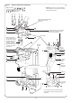
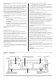
AUTOMATIC START-UP SEQUENCE
PRESENT
ON
TRIPPED TRIPPED
OFF OFF
Standby
Indicator
On
Hot Water
Select
Switch
Hot Water
Control
Stat
Hot Water
High Limit
Stat
Safety
Limit
Stat
Automatic
Start-up
Sequence
High/Low
Gas Valve
On
Ignition
Sequence
Stopped
Burner
Heat
Demand
(High Gas
Pressure)
Pump on.
Continues
5 minutes
after
Demand Off
Demand
Indicator
On
Heatbank
Overheat
Stat
All
Functions
Stopped
Stop
Burner
Flow
Switch
Air Pressure
Switch Test
Fan
On
Sense Air
Pressur
e
Pilot Valve
Opens
Sense
Flame
Main Gas
V
alve Opens
Initiate Sparking Stop Sparking
Wait
(Pump &
F
an On)
Wait
(Pump &
F
an On)
Wait
(Pump On)
NORMAL
TRIPPED
H
B
C
D E
I
A
G
F
NORMAL NORMAL
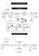
Domestic Hot Water Operational Flow Diagram
(CH Selected Off)
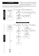
Central Heating Operational Flow Diagram
(HW Selected Off and Water Flow Switch off)
16. Operational Flow Diagrams
Note: The alpha references in these charts are to be used for cross-referencing when fault finding. See Section 17.
Frost
Thermostat
ON
ON
TRIPPED
ON
NORMAL
DEMAND
Standby
Indicator
On
Heating
Select
Switch
Room
Thermostat
Heating
Control
Stat
Safety
Limit
Stat
Automatic
Start-up
Sequence
Demand
Indicator
On
Minimum
Burner
Pressure
Ignition
Sequence
Stopped
Burner
Heat
Demand
(Low Gas
Pressure)
Heatbank
Overheat
Stat
All
Functions
Stopped
NORMAL
TRIPPED
J
Pump On.
Continues 5
minutes after
demand off
K
Diverter
Valve
On
N
L
M