
Technical data

44
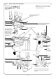
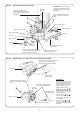
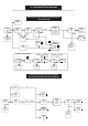
Fig. 47. Water to water heat exchanger.
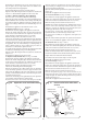
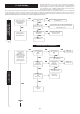
Ease top manifold downwards
10mm approx. to clear
pipework
Warning: There will be a small quantity of
water remaining in the pipework and water-
to-water heat exchanger.
Note: Screw Nos. 1 2 , 5 6 7 8 , 11 12
unscrew two full turns – Do not remove.
Screw Nos. 3 4 (Refer to Fig. 31) 9 10,
13 14 15 remove and retain.
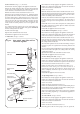
Support
bracket
Top manifold
Ease heating return
pipe downwards 10mm
into slip-joint in bottom
manifold. Ease pipe to
the left to clear top
manifold. Ease pipe
upwards 10mm approx.
to clear top manifold
and remove
“O” ring
seal
Slip
joint
Heating
return
pipe
“O” ring
seal
Water-to-
water heat
exchanger
Slip joint
Drain pipe
securing
clip
Bottom
manifold
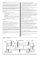
Front view of water to water heat exchanger
with manifolds in position and fixing screws
numbered
6
7
9
6
7
9
2
10
1
13
11 14
5
13
5
1
15
9
6 7 8
2
10
11 12 14
12
8
8
10
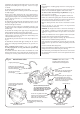
Unscrew flat face union securing top
manifold to inner casing pipework.
Remove sealing washer.
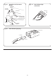
Water filter primary system