
Technical data


Using an approved jointing compound complying with
BS5292 fit the female half of the brass union to the
replacement gas valve inlet.
Fit the replacement gas valve in the reverse order ensure the
flange washer is renewed. Reconnect the pressure
compensating tube. Reassemble the appliance in reverse
order.
Turn on the gas supply at the service cock and check for gas
soundness.
Re-commission the appliance and check the burner setting
pressure. Refer to Section 12: Commissioning.
19. Pilot Filter.
If problems are experienced with the pilot filter fit a replacement
gas valve as described in Section 15.3.-18.
20. Circulating Pump. See Figs. 9, 16 and 45.
Check that the electricity supply to the appliance is turned off.
Remove the cabinet front panel, place the facia and control box
in the Service Position and lower the expansion vessel into the
Service Position, as described in Section 14.2 a, b and c.
Drain the heating circuit as described in Section 15.2 a.
Remove the pump cover and disconnect the electrical
connections. Release the cable clamp and remove the cable.
Withdraw the two securing clips from the pump body. Ease the
pump forwards about 10 mm off the “O” ring seals and remove
from the appliance.
WARNING: There will be a small quantity of water remaining in
the pump and pipework. Follow the procedure as described in
15.2. Discard the pump and “O” ring seals.
Fit new “O” ring seals. Fit a replacement pump in the reverse
order taking care to ensure the securing clips are properly
entered into the slots and not scoring the O-rings on entry. A
smear of lubricant on each O-ring will ease the re-assembly.
Check the pump head is set to maximum.
The pump head is a Grundfos 15/60. A replacement head may
be transferred to the special body. Take care not to mark the
mating surfaces.
Reconnect the cable and refit the cable clamp.
Open the valves, fill and repressurise the system as described in
Section 12.2.
Reassemble the appliance in the reverse order.
21. Water Diverter Valve. See Figs. 9, 16, 45 and 46.
Check that the electricity supply to the appliance is turned off.
Remove the cabinet front panel, place the facia and control box
in the Service Position and lower the expansion vessel into the
Service Position, as described in Section 14.2 a, b and c. Remove
the facia as described in Section 15.1 .
Drain the heating circuit as described in Section 15.2 a.
Remove the circulating pump as described in Section 15.3 - 20.
Note: It is not necessary to disconnect the electrical cable. The
cable length is sufficient to allow the pump head to rest on top of
the appliance. Do not allow the pump head to be suspended by
the cable. Secure the pump head.
Pull off the Molex plug marked X7 ‘Diverter Valve’ from the
control board located in the control box. Release the strain relief
bush by compressing the loose section of the bush and carefully
withdraw the lead from the control box.
Using a pair of long nose pliers, remove the two clips securing
the 6 mm copper pressure pipe, to the top left hand corner of the
valve and pump connection. Retain the clips. Ease the pressure
pipe out of the connections and clear of the appliance.
Retain the pressure pipe.
Unscrew the four fixing screws securing the water diverter valve
to the bottom manifold. The bottom right hand screw is
accessible using a “chubby” type screwdriver. Remove the water
diverter valve clear of the appliance. Discard the valve and “O”
ring seals. Retain the fixing screws.
WARNING. There will be a small quantity of water remaining in
the valve and lower manifold. Follow the procedure as described
in 15.2.
NOTE: Three new “O” ring seals are provided with the
replacement valve. Two of the “O” rings are identical in diameter
and cross - section and are required for the outer ports. The third
“O” ring is smaller in diameter and cross-section and will seal the
centre port.
IMPORTANT: Fit the two larger diameter “O” rings into the outer
locations on the replacement valve. Fit the smaller diameter “O”
ring over the centre spigot on the bottom manifold. Ensure the
“O” ring is located correctly against the shoulder on the centre
spigot.
Fit the replacement valve in reverse order ensure the four fixing
40
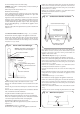
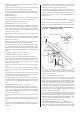
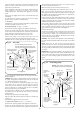
Pull off the pressure
compensating tube
Gas service
cock
Gas inlet
union fitting
Remove the female half
of the brass union fixed
to the gas valve inlet
Pilot supply tube
Unscrew retaining screws from the
solenoid electrical connection plugs. Pull
each plug off its respective set of terminals
Remove extended
hexagonal head
screws (4)
Flange
Replace the “O” ring
seal when changing
the gas valve
Fig. 44. Gas valve.
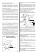
Cable
clamp
Remove
pump cover
and
disconnect
electrical
connections
Pump head. To
remove ease
forwards about
10mm off the “O”
ring seals
Flat clip
securing pump
inlet pipe
Securing
clip
Open vent
connection
(if fitted)
Warning: There will be a small quantity of
water remaining in the pump and pipework
Open vent
pipe (if fitted)
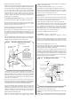
Two “O” ring
seals. Remove
and replace
with new “O”
ring seals
Securing
clip –
copper
pressure
pipe
Securing
clip
Copper
pressure
pipe
3
Fig. 45. Circulating pump.
4