
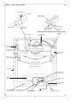
Technical data


the heat exchanger clear of the inner casing.
WARNING: There will be a small quantity of water remaining in
the heat exchanger.
Follow the procedure as described in 15.2.
Discard the heat exchanger.
Fit the replacement heat exchanger in the reverse order using
new fibre sealing washers. Ensure the washers are in place and
the heat exchanger correctly aligned.
Tighten the union connections. Refit the access cover to the left
hand side of the combustion chamber and replace the fibre
insulation pad. Refit the combustion chamber cover. Refit the
overheat thermostat phial with a layer of heat sink compound.
Refer to Wiring Diagram Fig. 9). Reassemble the appliance in the
reverse order.
Open the valves, fill and re-pressurise the system as described in
Section 12.2.
4. Combustion Chamber Insulation. See Figs. 9, 16, 17, 35 and 37.
Check that the electricity supply to the appliance is turned off.
Remove the cabinet front panel, place the facia and control box
in the Service Position, lower the expansion vessel into the
Service Position and remove the inner casing cover, as described
in Section 14.2 a, b, c and d.
Drain the heating circuit as described in Section 15.2 (a).
Remove the combustion chamber cover as described in Section
14.2 (g).
Remove the gas to water heat exchanger as described in Section
15.3 - 3.
Remove the fibre insulation pads from the combustion chamber
side, rear and front sections and discard.
Fit replacement fibre insulation pads in the reverse order.
Note: The fibre pads are fragile take care they are not damaged.
Ensure the insulation pad fitted to the combustion chamber
cover has the pilot observation hole correctly aligned.
Reassemble the appliance in the reverse order.
Open the valves, fill and re-pressurise the system as described in
Section 12.2
5. Main Burner. See Figs. 16, 34 and 35.
Check that the electricity supply to the appliance is turned off.
Remove the cabinet front panel, place the facia and control box
in the Service Position, lower the expansion vessel into the
Service Position and remove the inner casing cover, as described
in Section 14.2 a, b, c and d.
Remove the combustion chamber cover and main burner
assembly as described in Sections 14.2 g and h.
Discard the burner.
Fit a replacement main burner in the reverse order. Ensure the
main burner is fitted correctly on the main burner injector
located at the back of the inner casing. Reassemble the
appliance in the reverse order.
6. Main Burner Injector. See Figs. 16, 35 and 38.
Check that the electricity supply to the appliance is turned off.
Remove the cabinet front panel, place the facia and control box
in the Service Position, lower the expansion vessel into the
Service Position and remove the inner casing cover, as described
in Section 14.2 a, b, c and d.
Remove the combustion chamber cover and main burner
assembly as described in Sections 14.2 g and h.
Unscrew the brass injector at the rear of the inner casing and
discard.
Fit the replacement injector in the reverse order. Thread sealing
compound is not required. Reassemble the appliance in the
reverse order.
7. Pilot Burner. See Figs. 16, 34, 35 and 39.
Check that the electricity supply to the appliance is turned off.
Remove the cabinet front panel, place the facia and control box
in the Service Position, lower the expansion vessel into the
Service Position and remove the inner casing cover, as described
in Section 14.2 a, b, c and d.
Remove the combustion chamber cover as described in Section
14.2 g.
Unscrew the two screws securing the pilot burner to the main
35
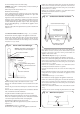
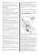
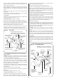
Front union connection
Fibre sealing washer
Fibre sealing washer
Rear union connection
Gas to water heat
exchanger
Remove access cover
Warning: There will be a small quantity of
water remaining in the heat exchanger.
Fixing screw
Remove left-hand fibre insulation pad
Fig. 36. Gas to water heat exchanger.
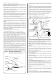
Gas to water heat exchanger
Combustion chamber
rear insulation pad
Main burner
Combustion chamber
side insulation pads
Fig. 37. Combustion chamber insulation.
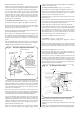
Main burner injector
Rear of inner
casing
Fig. 38. Main burner injector.