
Technical data


30
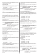
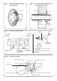
Flame length 18-20mm
Pilot assembly fixing screws
Pilot head
Pilot injector
Pilot assembly
Spark electrode
Spark electrode guide
Spark electrode lead
Spark electrode location clip groove
Fig. 34. Pilot burner assembly.
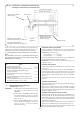
230V electrical
supply to pilot
solenoid
230V electrical
supply to On/Off
solenoid
Inlet pressure
test point
High/Low burner
pressure adjusting
screws under plastic
cap. See below.
Burner setting
pressure test point
High/Low
solenoid
B
A
C
Retaining
screw
230v electrical
supply plug to
High/Low solenoid
A – Adjustment for domestic hot water (High) gas
pressure setting
B – Adjustment for heating (Low) gas pressure
setting
C – Plastic cap
Fig. 33. Gas control valve adjustment.
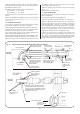
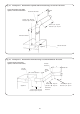
Duct assembly
Air duct
Flue duct
Rubber sealing
gasket
Flue terminal
Flue centring ring
Seal
External wall
Fig. 32. Duct and terminal assembly for
internal fitting of the flue.
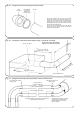
Rubber sealing gasket
Clamping ring
Flue terminal
Fig. 31. Terminal assembly for internal
fitting of the flue.