
Technical data


27
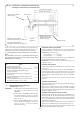
Flue
terminal
Air duct
Flue restrictor
ring. Refer to
Section 11.3
for correct size
Fit the flue restrictor ring into the flue terminal.
Ensure the air duct is fully engaged in the flue ter-
minal and the restrictor ring is located firmly
between the end of the air duct and flue terminal.
Drill through the holes in the flue terminal into the
air duct with the drill provided.
Apply a smear of silicone sealant to the outside
end of the air duct and fit into the flue terminal
using the screws provided.
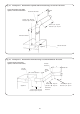
Fig. 24. Fixing the flue restrictor ring into the flue terminal.
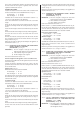
The two flue lengths, when added
together, must not exceed 2300mm
First 90° flue bend
A
ir d
u
c
t =
(
C –
5
8
) m
m
F
lu
e
d
u
c
t =
(
C –
1
4
) m
m
A
ir d
u
c
t =
(
B –
1
6
6
) m
m
F
lu
e
d
u
c
t =
(
B –
1
5
2
) m
m
Second 90° flue bend
Outside
wall
Appliance
B 210mm minimum
C
Fig. 25. Flue Option 5. Extension horizontal flue using a second 90° flue bend.
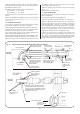
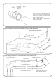
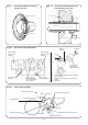
Flue elbow and air duct
fixing screws
Flue elbow and air duct
fixing screws
Fixing screws not
required for flue duct
Air duct (100mm diameter)
Flue duct (60mm diameter)
The flue duct does not require fixing screws when
located between the flue bends
Ensure that the ducts are correctly
located into the socketed joints.
Seal the joints with a smear of
silicone sealant.
Fig. 26. Fitting the flue bends to the intermediate sections of the flue duct.