
Technical data

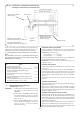


Measure accurately the distance from the rear of the appliance,
previously marked on the floor, to the centre of the first 90° flue
bend. Dimension D. See Fig. 30.
The minimum dimension must not be less than 105 mm.
Air duct length = D + 82 mm.
Flue duct length = D + 80 mm.
Cut air and flue ducts to length. Do not cut the drilled end of the
air duct.
Continue the installation by following the procedure for the flue
option chosen. Refer to Section 11.5, 11.6.2, 11.6.3, 11.6.4,
11.6.5, or 11.6.6.
11.7 INTERNAL FLUE FITTING.
If it is required to install the flue system from inside the building
the hole in the wall must be 150 mm ( 6 in ) diameter.
Measure and cut the ducts as previously described. See Section 11.3.
Assemble the air and flue ducts to the flue terminal and flue
bend as previously described. See Section 11.4 and 11.5.
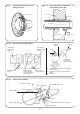
Fit the rubber sealing gasket to the flue terminal. Centralise the
gasket and tighten the clamping ring. See Fig. 31.
Pass the assembly through the wall from inside the building so that
the gasket flange is against the outside face of the wall. See Fig. 32.
Align the flue outlet or flue bend with the flue position on rear of
the appliance. Ensure the flue outlet or flue bend is correctly
located against the stop. See Fig. 23.
Tighten the clamping screw accessible on top of the inner casing.
See Fig. 14.
Make good the internal brickwork.
11.8 FINAL INSTALLATION.
Check that all the water connections and the gas connection
have been tightened.
Facia Mounted Programmer (where applicable).
Remove the facia panel as described in Section 11.3. Refer to Fig. 14.
Unplug the Operating Switch connection at the control board .
Unscrew and retain the four nuts and washers securing the
switch mounting plate to the facia. See Fig. 9. Remove the plate.
Fit the programmer to the facia and fix using the four nuts and
washers.Plug the lead into the connection on the control board.
See Fig. 12. The programmer can be set when the electricity
supply has been turned on at the commissioning stage.
Connect the mains electricity supply to the appliance and
connect any room and/or frost thermostats. Refer to Section 10,
Fig. 9 and 12. The leads from the thermostats must pass through
holes provided in the control box at the right hand side and be
clamped using the strain relief bushes provided in the pack.
26
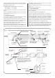
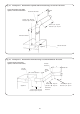
Fig. 23. Typical extension horizontal side and rear flue assemblies.
Rear of appliance
Flue bend, air duct and
flue duct fixing screws
Air duct and flue
duct fixing screws
Air duct terminal
fixing screws
Do not apply
silicone sealant
at this point
Smear silicone
sealant on the
air and flue duct
joints
Flue
terminal
External wall
Side Flue
Assembly
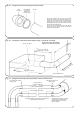
Top of appliance
inner casing
Do not apply silicone
sealant at these joints
Ensure that the ducts are
correctly located into the
socketed joints. Seal the
joints with a smear of
silicone sealant
Air duct (100mm diameter)
Flue duct (60mm diameter)
For flue ducts over
1500mm long, fit a flue
support halfway along
the horizontal section
Flue
bend
Rear of appliance
Apply a smear of
silicone sealant to
these joints
Flue adaptor
Flue position
located on rear of
inner casing
Air duct
Flue duct
Flue adaptor must be fitted into the flue
position located on the rear of the inner
casing for all rear flue applications or when
a straight section of flue duct is required
before the first flue bend
External wall
Rear Flue
Assembly
Top of appliance
inner casing
Do not apply
silicone sealant at
these joints
See Enlarged Detail