
Technical data


19
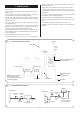
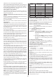
Central Heating
Flow Valve
Central Heating
Return Valve
Pressure Relief
Valve
By-pass Adjusting
Screw.
Turn clockwise
to close
Manual Air
Vent
Fig. 17. Central heating flow and return valves,
by-pass adjustment, pressure relief and
manual air vent.
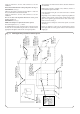
Fig. 15. Discharge pipe connection for sealed
system.
Base plate
Rear view of
appliance
Cabinet side
panel
Pressure relief
drain connection
Discharge pipe must be 22mm
copper fall continuously throughout
its length and discharge to a safe
visible position
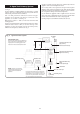
Remove securing clip
Ease pump head forwards
off the “O” ring seals
Remove securing clip
“O” ring seals
Disconnect the flexible hose from the bottom
manifold and fit the open vent pipe supplied as
an optional extra
Fig. 18. Open vent position and pipework.
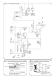
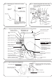
Circulating pump
Domestic water expansion
vessel connection
T
o lower the expansion vessel
follow instructions 1 to 4:
1. Remove cabinet front panel.
Refer to Fig. 12.
2. Raise facia and control box
into the service position.
Refer to Fig. 12.
3. Unscrew one fixing screw.
4. Lower expansion vessel to
rest on the floow.
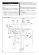
By-pass adjusting screw
Pressure relief valve
Primary manual air vent
Inner casing fixing screws (4)
Central heating flow valve
Central heating return
valve
Control Box
Mains cold water inlet
valve
Heatbank overheat
thermostat reset button
Refer to figure 17 for
details of this area
Water diverter valve
Gas valve
Gas service cock
Flexible hose
Domestic drain
Gas valve electrical supply plug
Heatbank
Hot water and heatbank
overheat thermostat pocket
Expansion vessel lowered into
service position
System pressure
gauge
Hinge
Facia
Fig. 16. Layout of components with expansion vessel in service position.
Safety temperature limiter
thermostat reset button