
Technical data
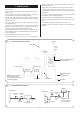

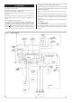
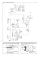
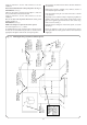


Refer to Figs. 9, 10, 11 and 12.
10.1 Mains Supply 230V ~ 50Hz 270 watts. External Fuse 3A.
Internal Fuse 3.15A fast blow 20mm long.
10.2 The electrical supply must be connected by a qualified
electrician.
10.3 A fused double pole isolator with a contact separation of
3mm in all poles MUST be used to supply the appliance and
controls.
10.4 The appliance must be earthed.
10.5 Mains Cable: PVC insulated 0.75mm
2
(24x0.20mm) to BS
6141 Table 15. If a new cable is needed it must be connected into
the terminals marked L (Brown or Red lead), N (Blue or Black
lead) and (Green/Yellow or Green) and be held securely in the
cable clamp. Ensure the Earth conductor is longer than the
current carrying conductor, so that if the cable slips in its
anchorage, the current carrying conductors become taut before
the Earth conductor. For access refer to Section 14.
10.6 The wiring between the appliance and the electrical supply
shall comply with current IEE Wiring Regulations, and any local
regulations which apply.
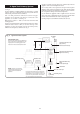
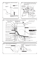
10.7 If a room and/or frost thermostat is to be fitted refer to
Fig. 11.
10.8 The thermostats must be suitable for use on mains voltage.
10.9 A facia mounted programmer is available as an optional
extra. Instructions are supplied with the programmer kit.
See Fig. 12.
10.10 A timeswitch or programmer can be fitted externally to
the appliance.
10.11 SAFETY CHECK.
After installation or in the event of an electrical fault the
electrical system shall be checked for short circuits, fuse failure,
incorrect polarity of connections, earth continuity and resistance
to earth.
10. Electrical
14
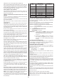
MAINS
IN
HOT WATER
CONTROL STAT
br
X12
HEATING
CONTROL STAT
OPERATING
SWITCH
STANDBY
INDICATOR
DEMAND
INDICATOR
CONTROL
FACIA
br
w
g
gy
bl
br
X11
br
bl
gy
CN3
CN4 CN5
CN2
br
w
g
CN1
br bl br bl gy br y
HT
TAG
IGNITION
BOARD
br w g
AIR
PRESSURE
SWITCH
SAFETY LIMIT
STAT
ELECTRODE
FAN
HOT WATER
HIGH LIMIT
STAT
FLOW
SWITCH
PUMP
DIVERTER
VALVE
PILOT HILO MAIN
GAS VALVE
HEATBANK
OVERHEAT
STAT
1
gy
1
CONTROL
BOARD
ROOM
THERMOSTAT
(OPTIONAL)
FROST
THERMOSTAT
(OPTIONAL)
EARTH PLATE
w
g
br
w
C
NC
NO
gy
X2
X13
X7
X15
X4
X14
X1
X8
X5
X10
X3
1
X6
1
1
1
1
1
w
w
1
bk
bk
bk
bk
pk
pk
bl
br
br
bl
bk
bk
br
bl
or
or
bl
br
gy
X16
1
r
r
1
1
1
Fig. 9. Wiring diagram.