
Technical data

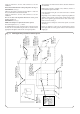


See Fig. 6 and 7.
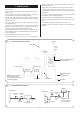
7.1 The system must comply with the requirements of BS 6798
and BS 5449:1.
7.2 The appliance must not be operated without the system
being full of water, properly vented and pressurised.
7.3 The safety valve operates at 3bar (45lb/in
2
). The discharge
must be directed away from electrical items or where it might be
a hazard to the user.
7.4 The pressure gauge indicates the system pressure which
must be maintained.
7.5 The 12 litre expansion vessel is charged to 0.5 bar and is
suitable for a static head of 5m (17.5ft). The pressure can be
increased if the static head is greater than 5m (17.5ft).
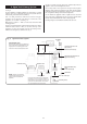
7.6 With an initial system pressure of 0.5 bar, a system capacity
of about 104 litres can be accommodated.Refer to BS 7074 Part 1
for more information.
7.7 The filling point must be at low level. See Fig 6.
7.8 Water loss must be replaced. See Fig 7. The connection
should be made in the central heating return as close to the
appliance as possible.
7.9 The make-up vessel must be fitted with a non-return valve.
7.10 Repeated venting loses water from the system. It is
essential that this water is replaced and the system pressure
maintained.
7.11 There must be no connection to the mains water without
the authority of the local Water Company.
7.12 The pump is set at maximum and must not be adjusted.
7.13 Connections in the system must resist a pressure of up to
3 bar.
7.14 Radiator valves must conform to BS 2767(10): 1972.
7.15 Other valves used should conform to the requirements of
BS 1010.
7. Sealed System
11
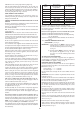
Heating return
Non return
valve
Non return
valve
Hose union
Test cock
Temporary hose
Stop cock
Auto
air vent
Heating return
Stop
cock
Fill point
Non return
valve
Make up
vessel
300 mm (12 in) min.
above the highest
point of the system.
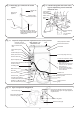
Fig. 7. System filling and make-up.
Top-up Bottle
Non-Return
Valve
Hot Water
Out
Mains
Cold
Water
Lockshield Valve Radiator Valve
Heating Flow
Heating Return
Spherical Plug Ball Valve for
appliance servicing
British Standard Stop
Valve.
Fixed spindle type
Water Main
NOTE: A drain cock should
be installed at the lowest
point of the heating circuit and
beneath the appliance.
Appliance
(Refer to
Fig. 1
for appliance
Water Flow
diagram)
Fig. 6. Sealed primary water system.