Highflow 400 RSF FLOOR STANDING COMBINATION APPLIANCE FOR CENTRAL HEATING AND MAINS FED DOMESTIC HOT WATER INSTALLATION AND SERVICING INSTRUCTIONS GC NUMBER 47 311 18 BOILER OUTPUT To Hot Water On/Off Control Maximum 24.0 kW (82,000 Btu/h) To Central Heating On/Off Control Range Rated Minimum 8.8 kW (30,000 Btu/h) Maximum 24.
Contents 1. 2. 3. 4. 5a. 5b. 5c. 6. 7. 8. Installation Requirements .......................................... Page 2 General Information .................................................... Page 2 Data Tables .................................................................... Page 5 Siting the Appliance .................................................... Page 8 Flue Terminal Position ................................................ Page 8 Flue Options ....................................................
The complete installation including the gas meter must be tested for soundness and purged. See BS 6891. Gas Discharge Rate (m3/hr) Total Length of Gas Supply Pipe (metres) 3 6 9 8.7 5.8 4.6 18.0 12.0 9.4 2.11 SYSTEM NOTES. WARNING: CHECK THAT NO DIRT IS LEFT IN EITHER THE GAS OR WATER PIPEWORK AS THIS COULD CAUSE DAMAGE TO THE APPLIANCE. THOROUGHLY FLUSH THE HEATING SYSTEM, AND THE WATER SUPPLY IN ACCORDANCE WITH THE RECOMMENDATIONS OF BS 7593:1992.
With the system at the temperature set by the Temperature Control Knob,on the facia, the burner will cycle to maintain output to the system. If the system no longer requires output to maintain the desired room temperature, the burner will extinguish. The pump will continue to run for about five minutes to dissipate the residual heat from the appliance and then switch off.
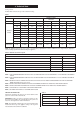
3. Technical Data See Fig. 2 and 3. The Data Plate is fixed to the top of the control box casing. Table 1 NOMINAL BOILER RATINGS (10 minutes after lighting the appliance) BURNER SETTING OUTPUT INPUT PRESSURE MODE GAS RATE kW Btu/h kW Btu/h m bar. in. wg. m3/h ft3/h 8.8 (30,000) 12.1 (41,300) 1.0 0.4 1.11 40.0 11.0 (37,000) 15.0 (51,000) 3.5 1.4 1.45 51.0 13.0 (44,350) 17.4 (59,400) 5.2 2.1 1.55 54.5 HEATING 15.0 (51,200) 19.7 (67,000) 5.5 2.2 1.90 67.5 RANGE 17.
Table 4 AVAILABLE PUMP HEAD BOILER OUTPUT HEAD MIN. FLOW RATE kW Btu/h Metres Feet L/min. Gal/Min. 8.8 (30,000) 6.1 20.0 11.5 2.5 11.0 (37,000) 5.4 17.5 14.0 3.1 13.0 (44,350) 4.9 16.0 17.0 3.7 HEATING 15.0 (51,200) 4.2 13.5 19.5 4.3 RANGE 17.0 (58,000) 5.3 17.0 15.0 3.3 19.0 (64,800) 4.85 16.0 17.0 3.7 21.0 (71,500) 4.4 14.5 19.0 4.2 23.0 (78,500) 5.2 17.0 16.0 3.5 24.0 (82,000) 5.0 16.5 16.5 3.
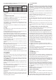
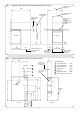
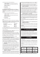
Fig. 2. Appliance cabinet dimensions and minimum clearances required. 1200 Space required for installation 910 Space required for installation Space required for servicing 610 Space required under fixed surface Side View 1310 860 Cabinet Height Wall 10 450 Surface may be fixed after installation.
4. Siting The Appliance 4.1 THE APPLIANCE MAY BE INSTALLED IN ANY ROOM ALTHOUGH PARTICULAR ATTENTION IS DRAWN TO THE REQUIREMENTS OF THE CURRENT I.E.E. WIRING REGULATIONS AND, IN SCOTLAND, THE ELECTRICAL PROVISIONS OF THE BUILDING REGULATIONS APPLICABLE IN SCOTLAND, WITH RESPECT TO THE INSTALLATION OF APPLIANCES IN ROOMS CONTAINING BATHS OR SHOWERS. Installation Service Above the appliance 450 mm 10 mm In front 600 mm 600 mm 5 mm 5 mm 300 mm 5 mm Right side Left side 4.
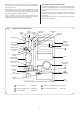
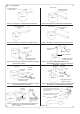
Fig. 5. Flue options. 90° flue bend Standard flue length 100 to 500mm Standard flue length 100 to 950mm Appliance Appliance Frame 1: Flue Option 1. Standard Horizontal Rear Flue. Frame 2: Flue Option 2. Standard Horizontal Side Flue. 90° flue bend Maximum flue length 3000mm Maximum flue length 3000mm Appliance Appliance Frame 3: Flue Option 3. Extension Horizontal Rear Flue. Frame 4: Flue Option 4. Extension Horizontal Side Flue.
The following items are included in this flue kit: 1 – Air duct 700 mm long (including fixing length inside appliance cabinet). 1 – Flue duct 700 mm long (including fixing length inside appliance cabinet). 1 – Balanced Flue Terminal. 1 – Flue Adaptor. 2 – Fixing screws. 1 – Tube of silicone sealant. 5b.2 Standard Horizontal Side Flue Kit. See Fig. 5 Frame 2. The maximum flue length when measured from the RIGHT or LEFT-HAND side of the appliance cabinet is 950 mm.
should be made in the central heating return as close to the appliance as possible. 7.9 The make-up vessel must be fitted with a non-return valve. 7.10 Repeated venting loses water from the system. It is essential that this water is replaced and the system pressure maintained. 7.11 There must be no connection to the mains water without the authority of the local Water Company. 7.12 The pump is set at maximum and must not be adjusted. 7.13 Connections in the system must resist a pressure of up to 3 bar. 7.
8.4 The feed and vent pipe must rise continuously from the appliance to the feed and expansion cistern. 8.5 A safety valve is not required on an open vented system. With the safety valve left in position a pipe must be fitted which terminates such that any discharge does not cause a hazard to the occupants or damage to electrical components. 8.
9.11 The supply of hot and cold mains water direct to a bidet is permitted, subject to local Water Company requirements, provided that the bidet is of the over-rim flushing type. The outlet(s) should be shrouded and unable to have any temporary hand held spray attached. No anti-syphonage arrangements are necessary. 9.12 As the maximum temperature of the hot water heat exchanger is limited by the control circuit, there is normally no need for water treatment to prevent scale accumulation.
anchorage, the current carrying conductors become taut before the Earth conductor. For access refer to Section 14. 10.6 The wiring between the appliance and the electrical supply shall comply with current IEE Wiring Regulations, and any local regulations which apply. 10.7 If a room and/or frost thermostat is to be fitted refer to Fig. 11. 10.8 The thermostats must be suitable for use on mains voltage. 10.9 A facia mounted programmer is available as an optional extra.
5 5 Live 4 4 3 3 2 2 Remove link Room thermostat black red X14 (PIN 1) N brown X12 (PIN 2) grey HOT WATER white X12 (PIN3) OPTIONAL LINK Fig. 11. Room/frost thermostats and programmer.
Before continuing with the installation it will be necessary to decide which flue option is suitable. Refer to Section 5b and Fig. 5. Having decided upon the most suitable flue option for the installation, the position of the hole for the flue must now be marked on the wall/walls. FLUE OPTION 1. See Fig. 5. The location of the centre point position for the Rear Flue is obtained from the flue centre-lines previously marked. This is the Rear Flue centre point position. See Fig. 13. FLUE OPTION 2. See Fig. 5.
The position for the hole/holes for the flue should be marked on the wall/walls. Mark the wall where the flue will terminate to suit the installation. This is the Side Flue Extension centre point position. See Fig. 13. FLUE OPTION 8. See Fig. 5. Follow the procedure as described in Flue Option 6 ensure the flue system remains vertical and horizontal. Mark the wall where the flue will terminate to suit the installation. This is the Rear Flue Upwards Extension centre point position. See Fig. 13.
11.3 FIXING THE APPLIANCE FOR ALL FLUE OPTIONS. To gain access to the appliance remove the cabinet front and top panel and place the facia and control box in the Service Position : i) Lift the cabinet front panel off the top location and clear the lower return over the kick strip. See Fig. 14. ii) Unscrew the two screws securing the facia to the outer edges of the cabinet accessible under the facia. Ease the facia and control box forwards on the slide rails until fully extended. See Fig. 14.
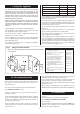
Fig. 15. Discharge pipe connection for sealed system. Fig. 17. Central heating flow and return valves, by-pass adjustment, pressure relief and manual air vent. Cabinet side panel Central Heating Flow Valve Rear view of appliance Central Heating Return Valve Pressure relief drain connection Manual Air Vent Base plate Discharge pipe must be 22mm copper fall continuously throughout its length and discharge to a safe visible position By-pass Adjusting Screw.
Withdraw the two securing clips from the pump body. East the pump forwards about 10mm off the “O” ring seals. It is not necessary to disconnect the electrical cable. The cable is sufficient to allow the pump head to rest on top of the appliance. Do not allow the pump head to be suspended by the cable. Secure the pump head. See Figs. 18 and 45. NOTE: INTERNAL FLUE FITTING KIT. If the Internal Flue Fitting Kit is to be used refer to Section 11.
Apply a smear silicone sealant around the inside of the air duct. the end of the air duct and flue terminal. See Fig. 24. Drill through the holes in the flue terminal into the air duct with the drill provided. Apply a smear of silicone sealant to the end of the air duct and fix into the flue terminal using the screws provided. See Fig. 22. Fit the flue duct into the flue bend. Ensure it is located correctly against the stop. Drill two holes through the holes in the flue bend. See Fig. 22.
Fig. 20. Flue Option 3. Standard horizontal side flue. Flue Option 4. Extension horizontal side flue. Flue duct = (A + 284) mm Air duct = (A + 244) mm Base outline of appliance marked on floor 90° flue bend 25 A Standard horizontal side flue – Flue Option 2: Dimension A = 1000 max. Front of appliance Distance from the side of the base outline of the appliance to the outside surface of the wall 65 Outside of wall Extension horizontal side flue – Flue Option 4: Dimension A = 3000 max.
Fit the flue adaptor to the air and flue ducts and assemble the flue system. Follow the procedure as described in Section 11.3 and 11.4 to fit the flue adaptor and assemble the flue system. The flue system is now assembled. From inside or outside the dwelling pass the flue assembly through the hole/holes in the wall/walls. Temporarily support the flue system, ensure it is horizontal and will align with the flue position, located on the rear of the appliance.
The flue duct must fit correctly between the flue bends. The duct is trapped between the flue bends and does not require fixing screws. See Fig. 26. Follow the procedure for fixing the assembly to the appliance as described in Section 11.6.2. The section of horizontal air and flue duct fitted adjacent to the first flue bend will not require expanded ends. Cut off the expanded ends from this section. SECOND FLUE LENGTH.
ii) A flue restrictor ring may be required. Refer to Section 11.3 to determine the size or whether the restrictor is necessary. iii) A flue adaptor MUST be fitted to connect the flue system to the appliance. Refer to the instructions in Section 11.4. Horizontal section of flue duct from the rear of the appliance casing to the first 90° flue bend. Fig. 21.
the appliance. Ensure the flue outlet or flue bend is correctly located against the stop. See Fig. 23. Tighten the clamping screw accessible on top of the inner casing. See Fig. 14. Make good the internal brickwork. 11.8 FINAL INSTALLATION. Check that all the water connections and the gas connection have been tightened. Facia Mounted Programmer (where applicable). Measure accurately the distance from the rear of the appliance, previously marked on the floor, to the centre of the first 90° flue bend.
Fig. 24. Fixing the flue restrictor ring into the flue terminal. Flue terminal Flue restrictor ring. Refer to Section 11.3 for correct size Air duct Fit the flue restrictor ring into the flue terminal. Ensure the air duct is fully engaged in the flue terminal and the restrictor ring is located firmly between the end of the air duct and flue terminal. Drill through the holes in the flue terminal into the air duct with the drill provided.
Fig. 27. Flue Option 6. Extension flue upwards and horizontal using a second 90° flue bend. The two flue lengths, when added together, must not exceed 2300mm Second 90° flue bend Outside wall C Air duct = (B – 166) mm Flue duct = (B – 152) mm Air duct = (C – 58) mm Flue duct = (C – 14) mm B 210mm minimum First 90° flue bend Appliance Fig. 28. Flue Option 7. Extension flue horizontal using a second and third 90° flue bend.
Fig. 29. Flue Option 8. Extension flue upwards and horizontal using a second and third 90° flue bend. The three lengths, when added together, must not exceed 1000mm Second 90° flue bend Outside wall C Air duct = (B - 166) mm Flue duct = (B - 152) mm B 210mm min imum Air duct = (C - 58) mm Flue duct = (C - 14) mm Air duct = (B - 166) mm Flue duct = (B - 152) mm Third 90° flue bend 210mm minimum B First 90° flue bend Appliance Fig. 30. Flue Option 9.
Fig. 31. Terminal assembly for internal fitting of the flue. Fig. 32. Rubber sealing gasket Duct and terminal assembly for internal fitting of the flue. Flue centring ring Flue terminal Seal Flue duct Flue terminal Duct assembly Air duct Clamping ring External wall Rubber sealing gasket Fig. 33. Gas control valve adjustment.
The appliance (as despatched) can accommodate a system volume of about 104 litres. Refer to BS 7074 Part 1. If the system volume is in excess of that accommodated by the expansion vessel fitted to the appliance then an extra vessel must be fitted as close as possible to the central heating return connection of the appliance. Any extra vessel fitted must be pressurised to the same figure as the integral vessel. If the expansion vessel fails then the specified replacement must be fitted . 12.3 PROGRAMMER.
e). If the Heating (Low) Gas Pressure has been changed set the indicator arrow on the data plate to the new setting. Balance the system so that the required temperature difference across the heating flow and return pipes is obtained. See Section 3, Table 4. Adjust the by-pass valve until the same temperature difference is obtained. See Fig. 16 and 17. This should be carried out with only a single radiator operating. If thermostatic radiator valves are fitted then one radiator should be left uncontrolled.
90° into the Service Position. Lodge in the Service Position on the outer locations. See Fig. 14. (c) Expansion Vessel. Unscrew one screw securing the expansion vessel support bracket to the right hand side panel. Lower the vessel gently until resting on the floor. See Fig. 16. (d) Inner Casing Cover. Repeat operations a, b and c. Unscrew the four screws securing the cover to the inner casing and lift off. See Fig. 16. (e) Fan. Repeat operations a,b,c and d.
Controls. Remove any dust or deposits using a soft brush. Take care not to mishandle any component connections. NOTE: Should any of the components be damaged they must be replaced before the service is completed. Refer to the appropriate item in Section 15 “Replacement of Parts.” After servicing, reassemble the appliance in the reverse order. Check that all components are in place and correctly fixed. See Fig.16 and 35.
the heat exchanger clear of the inner casing. WARNING: There will be a small quantity of water remaining in the heat exchanger. Follow the procedure as described in 15.2. Discard the heat exchanger. Fit the replacement heat exchanger in the reverse order using new fibre sealing washers. Ensure the washers are in place and the heat exchanger correctly aligned. Tighten the union connections. Refit the access cover to the left hand side of the combustion chamber and replace the fibre insulation pad.
Fig. 35. Inner casing assembly.
burner. Ease the pilot burner forwards sufficiently to allow a suitable tool to support it. The spark electrode is held in position with a clip. Ease the clip backwards and remove the spark electrode and retain. Unscrew the union nut securing the pilot pipe and ease the pipe clear. Remove the pilot injector which is a push fit inside the pilot burner and retain. Discard the pilot burner. Fit a replacement pilot burner in the reverse order.
Remove the facia as described in Section 15.1. Remove the spring clip from the thermostat pocket located on the front left hand side of the heatbank. NB. There are two thermostat phials fitted in the pocket. The Hot Water thermostat phial is at the front of the pocket. To identify the phial follow the capillary tube from the thermostat body located inside the control box (marked on the facia “Hot Water” thermostat) to the thermostat pocket.
of heat sink compound to the thermostat phial. Reassemble the appliance in the reverse order. 17. Air Flow Pressure Switch. See Figs. 9, 35, 43 and 53. Check that the electricity supply to the appliance is turned off. Remove the cabinet front panel and place the facia and control box in the Service Position, as described in Section 14.2 a and b. Remove the facia as described in Section 15.1. Carefully pull off the suction tubes and the electrical connections from the switch.
Service Position, as described in Section 14.2 a, b and c. Remove the facia as described in Section 15.1 . Drain the heating circuit as described in Section 15.2 a. Remove the circulating pump as described in Section 15.3 - 20. Note: It is not necessary to disconnect the electrical cable. The cable length is sufficient to allow the pump head to rest on top of the appliance. Do not allow the pump head to be suspended by the cable. Secure the pump head.
screws are correctly engaged. Replace the “O” ring seals and refit the pressure pipe. Ensure the securing clips are fully engaged in the locating holes. Reconnect the electric cable to the control board and replace the strain relief bush. Replace the circulating pump as described in Section 15.3-20. Open the valves, fill and repressurise the system as described in Section 12.2. Reassemble the appliance in the reverse order. the manifold to the water to water heat exchanger support bracket.
assembly to the support bracket with screw Nos.13 and 14. Fully tighten the screws fixing the “O” rings Nos. 11 and 12. See Figs. 47 and 48. Re-assemble the top manifold in the reverse order. Ensure the heating flow and heating return and hot water pipes are fully engaged. Ensure a new sealing washer and ‘“O”’ ring is fitted when reconnecting the union securing the top manifold to the inner casing pipework. Replace the manifold top fixing screws Nos.9 and 10. Tighten screws Nos.
Reassemble the manifold in the reverse order using new “O” rings to replace any “O” rings which have been disturbed. Use new sealing washers where appropriate. Ensure that all clips and screws are correctly refitted. Open the valves, fill and repressurise the system as described in Section 12.2. Reassemble the appliance in the reverse order. 24. Water to Water Heat Exchanger Bottom Manifold. Refer to Section 15.3-22 Water to Water Heat Exchanger.
Fig. 47. Water to water heat exchanger. Warning: There will be a small quantity of water remaining in the pipework and waterto-water heat exchanger. Note: Screw Nos. 1 2 , 5 6 7 8 , 11 12 unscrew two full turns – Do not remove. Screw Nos. 3 4 (Refer to Fig. 31) 9 10, 13 14 15 remove and retain. Ease top manifold downwards 10mm approx. to clear pipework 6 8 7 Unscrew flat face union securing top manifold to inner casing pipework. Remove sealing washer.
Fig. 48. Water to water heat exchanger. WARNING: There will be a small quantity of water remaining in the pipework and water-to-water heat exchanger Domestic drain clip Ease water to water heat exchanger and bottom manifold out of support bracket and clear of appliance Move assembly upwards 10mm approx.
30. Flow Switch. See Figs. 9, 16, 52 and 53. Check that the electricity supply to the appliance is turned off. Remove the cabinet front panel, place the facia and control box in the Service Position and lower the expansion vessel into the Service Position, as described in Section 14.2 a, b and c. Drain the hot water circuit as described in Section 15.2 b. Remove the facia as described in Section 15.1. Unplug the Molex plug marked X1 ‘Flow Switch’, from the control board.
Disconnect the room thermostat and frost thermostat if fitted, note the positions. Disconnect the mains supply at the terminal strip located bottom left hand corner of the control board, marked X11 ‘Mains Supply’. Unplug the Operating Switch or programmer if fitted, from terminal marked X12 ‘‘Programmer/Switch’’. Release the plastic catch at each mounting post pulling the printed circuit board forward approximately 3 mm to prevent the plastic catch from returning.
Fig. 54. Control box and thermostat bracket. Fig. 56. Neon indicator light connections. Thermostat capillaries Hot water thermostat Control box Connector X3 Hot water high limit thermostat Standby (Amber) Heating thermostat and clamping nut Clamping nut Fixing screws Fig. 55. Demand (Green) Mounting bracket Neon indicator light plugs. Locking clip slot. Locking clip Plug Connector Neon Lead.
16. Operational Flow Diagrams Note: The alpha references in these charts are to be used for cross-referencing when fault finding. See Section 17.
This Fault Finding Chart is to be used in conjunction with the Operational Flow Diagrams in Section 16. To find the fault, locate the point on the flow diagram at which the appliance has failed, e.g. letter B. Then read the corresponding section in the fault finding chart, e.g. Failure at point B. Note: Each section assumes that the appliance operates correctly up to that point. Note: 1. All voltage measurements are with respect to neutral unless otherwise stated. 2.
NO Does the fan run? Is there 230V at pin 1 of terminal X16? (Left black wire) NO Is there 230V at pin 2 of terminal X16? (Right black wire) NO Replace the control board YES YES Is there 230V at pin 2 of terminal X8? (Left orange wire) Hot water high limit stat has tripped. Investigate cause of overheating and/or replace NO FAILURE AT POINT B YES NO Replace the control board NO Fault with interboard wiring.
FAILURE AT POINT D Can a pilot flame be seen? NO Is there a gas supply to the appliance? NO Turn on the gas supply, bleed the system and check the pressure YES Is the pilot injector free from blockage? NO Replace the injector YES Replace the gas valve YES Does the main burner ignite? NO Has the sparking stopped? NO NO Live and Neutral supply could be reversed. Check connections to both boards and electrical spur.
FAILURE AT POINT G NO Set the operating switch (or programmer) to OFF, and turn both control knobs anti-clockwise to OFF. Does the pump continue to run for approx. 5 minutes? Whether the pump stops immediately or continues indefinitely the control board will be at fault. Replace control board YES FAILURE AT POINT H NO When the pump has stopped, turn on fully a hot water tap. Does the demand indicator illuminate? Is there 230V at pin 1 of terminal X1? (Blue wire) YES Is there approx.
START OF CENTRAL HEATING TEST Before tests ensure pump has stopped FAILURE AT POINT J NO Set the operating switch (or programmer) to HEATING and WATER and turn the heating control stat and room thermostat (if fitted) to maximum (but keep the hot water control stat in the OFF position). Does the DEMAND lamp illuminate? Is there 230V at pin 4 of terminal X12? (C.H.
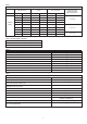
Key No. 1 2 3 4 5 6 7 8 9 10 11 12 13 14 15 16 17 18 19 20 21 22 23 25 26 27 28 29 30 31 32 33 34 35 36 37 38 39 40 GC No.
Worcester Heat Systems Limited, Cotswold Way, Warndon, Worcester WR4 9SW. Telephone: (01905) 754624 Fax: (01905) 754619 Technical Helpline (0990) 266241 This booklet is accurate at the date of printing but will be superseded and should be disregarded if specifications and/or appearances are changed in the interests of continued improvement. All goods sold are subject to our official Conditions of Sale, a copy of which may be obtained on application.